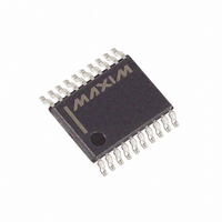
MAX1081BEUP+ Maxim Integrated Products, MAX1081BEUP+ Datasheet

MAX1081BEUP+
Specifications of MAX1081BEUP+
Related parts for MAX1081BEUP+
MAX1081BEUP+ Summary of contents
Page 1
... Typical Operating Circuit appears at end of data sheet. SPI and QSPI are trademarks of Motorola, Inc. MICROWIRE is a trademark of National Semiconductor Corp. ________________________________________________________________ Maxim Integrated Products For free samples and the latest literature, visit www.maxim-ic.com or phone 1-800-998-8800. For small orders, phone 1-800-835-8769. o 8-Channel Single-Ended or 4-Channel ...
Page 2
Single-Supply, Low-Power, 8-Channel, Serial 10-Bit ADCs with Internal Reference ABSOLUTE MAXIMUM RATINGS V to GND .............................................................. -0. DD_ ......................................................... -0.3V to 0.3V DD1 DD2 CH0–CH7, COM to GND.......................... -0. REF, REFADJ to ...
Page 3
Single-Supply, Low-Power, 8-Channel, Serial 10-Bit ADCs with Internal Reference ELECTRICAL CHARACTERISTICS—MAX1080 (continued +4.5V to +5.5V, COM = GND, f DD1 DD2 +2.5V at REF, REFADJ = DD1 A PARAMETER SYMBOL ...
Page 4
Single-Supply, Low-Power, 8-Channel, Serial 10-Bit ADCs with Internal Reference ELECTRICAL CHARACTERISTICS—MAX1080 (continued +4.5V to +5.5V, COM = GND, f DD1 DD2 +2.5V at REF, REFADJ = DD1 A MIN PARAMETER ...
Page 5
Single-Supply, Low-Power, 8-Channel, Serial 10-Bit ADCs with Internal Reference ELECTRICAL CHARACTERISTICS—MAX1081 (continued +2.7V to +3.6V, COM = GND, f DD1 DD2 +2.5V at REF, REFADJ = DD1 A PARAMETER SYMBOL ...
Page 6
Single-Supply, Low-Power, 8-Channel, Serial 10-Bit ADCs with Internal Reference ELECTRICAL CHARACTERISTICS—MAX1081 (continued +2.7V to +3.6V, COM = GND, f DD1 DD2 +2.5V at REF, REFADJ = DD1 A MIN PARAMETER ...
Page 7
Single-Supply, Low-Power, 8-Channel, Serial 10-Bit ADCs with Internal Reference TIMING CHARACTERISTICS—MAX1081 (Figures +2.7V to +3.6V, T DD1 DD2 PARAMETER SYMBOL SCLK Period SCLK Pulse Width High SCLK Pulse Width Low DIN ...
Page 8
Single-Supply, Low-Power, 8-Channel, Serial 10-Bit ADCs with Internal Reference (MAX1080 5.0V 6.4MHz; MAX1081: V DD1 DD2 SCLK at REF, 0.01µF capacitor at REFADJ INTEGRAL NONLINEARITY vs. DIGITAL OUTPUT CODE 0.12 0.08 ...
Page 9
Single-Supply, Low-Power, 8-Channel, Serial 10-Bit ADCs with Internal Reference (MAX1080 5.0V, f DD1 DD2 SCLK at REF, 0.01µF capacitor at REFADJ, T REFERENCE VOLTAGE vs. TEMPERATURE 2.5002 2.5000 MAX1080 2.4998 MAX1081 2.4996 2.4994 2.4992 2.4990 ...
Page 10
Single-Supply, Low-Power, 8-Channel, Serial 10-Bit ADCs with Internal Reference PIN NAME 1–8 CH0–CH7 Sampling Analog Inputs Ground Reference for Analog Inputs. COM sets zero-code voltage in single-ended mode. Must be 9 COM stable to ±0.5LSB. Active-Low Shutdown Input. Pulling ...
Page 11
Single-Supply, Low-Power, 8-Channel, Serial 10-Bit ADCs with Internal Reference Detailed Description The MAX1080/MAX1081 ADCs use a successive- approximation conversion technique and input T/H cir- cuitry to convert an analog signal to a 10-bit digital out- put. A flexible serial ...
Page 12
Single-Supply, Low-Power, 8-Channel, Serial 10-Bit ADCs with Internal Reference The T/H enters its tracking mode on the falling clock edge after the fifth bit of the 8-bit control word has been shifted in. It enters its hold mode on ...
Page 13
Single-Supply, Low-Power, 8-Channel, Serial 10-Bit ADCs with Internal Reference MAX1080 0 TO MAX1081 +2.500V CH7 ANALOG 0.01µF INPUT REFADJ 0.01µF 2.5V REF 4.7µF Figure 5. Quick-Look Circuit To quickly evaluate the MAX1080/MAX1081s’ analog per- formance, use the circuit of ...
Page 14
Single-Supply, Low-Power, 8-Channel, Serial 10-Bit ADCs with Internal Reference Table 3. Control-Byte Format BIT 7 BIT 6 BIT 5 (MSB) START SEL2 SEL1 BIT NAME DESCRIPTION The first logic “1” bit after CS goes low defines the beginning of ...
Page 15
Single-Supply, Low-Power, 8-Channel, Serial 10-Bit ADCs with Internal Reference CS SCLK 1 4 SEL SEL SEL UNI/ SGL/ DIN BIP START HIGH-Z SSTRB RB1 HIGH-Z DOUT IDLE Figure 6. Single-Conversion Timing ___________Applications Information When power is ...
Page 16
Single-Supply, Low-Power, 8-Channel, Serial 10-Bit ADCs with Internal Reference CS t CSS t CSO SCLK DIN t DOE DOUT t STE SSTRB Figure 7. Detailed Serial-Interface Timing Table 4. Software-Controlled Power Modes PD1/PD0 MODE Full ...
Page 17
Single-Supply, Low-Power, 8-Channel, Serial 10-Bit ADCs with Internal Reference CS DIN S CONTROL BYTE SCLK HIGH-Z DOUT HIGH-Z SSTRB Figure 8. Continuous 16-Clock/Conversion Timing 1.50 1.25 1.00 0.75 0.50 0.25 0 0.0001 0.001 0.01 0.1 TIME ...
Page 18
Single-Supply, Low-Power, 8-Channel, Serial 10-Bit ADCs with Internal Reference fast power-down (FASTPD) or reduced-power (REDP) mode instead of in full power-up can further reduce power consumption. This is achieved by using the sequence shown in Figure 12a. Figure 10b ...
Page 19
Single-Supply, Low-Power, 8-Channel, Serial 10-Bit ADCs with Internal Reference +3.3V 24k 510k 100k 0.01µF Figure 13. MAX1081 Reference-Adjust Circuit OUTPUT CODE FULL-SCALE TRANSITION 111 110 101 00 ...
Page 20
Single-Supply, Low-Power, 8-Channel, Serial 10-Bit ADCs with Internal Reference Table 5. Full Scale and Zero Scale UNIPOLAR MODE Full Scale REF COM SUPPLIES V GND DD1 *R = 10Ω V GND V COM DD1 DD2 MAX1080 ...
Page 21
Single-Supply, Low-Power, 8-Channel, Serial 10-Bit ADCs with Internal Reference 1 CH0 2 CH1 3 CH2 4 ANALOG CH3 MAX1080 INPUTS MAX1081 5 CH4 6 CH5 7 CH6 8 CH7 9 COM V 10 SHDN DD1 Figure 17. QSPI Connections ...
Page 22
Single-Supply, Low-Power, 8-Channel, Serial 10-Bit ADCs with Internal Reference CS SCLK START SEL2 SEL1 SEL0 DIN SSTRB DOUT Figure 19. MAX1080/MAX1081-to-TMS320 Serial Interface Signal-to-Noise Plus Distortion (SINAD) SINAD is the ratio of the fundamental input frequency’s RMS amplitude to ...
Page 23
Single-Supply, Low-Power, 8-Channel, Serial 10-Bit ADCs with Internal Reference ________________________________________________________Package Information Note: The MAX1080/MAX1081 do not have an exposed die pad. ______________________________________________________________________________________ 23 ...
Page 24
... Maxim cannot assume responsibility for use of any circuitry other than circuitry entirely embodied in a Maxim product. No circuit patent licenses are implied. Maxim reserves the right to change the circuitry and specifications without notice at any time. 24 ____________________Maxim Integrated Products, 120 San Gabriel Drive, Sunnyvale, CA 94086 408-737-7600 © 2000 Maxim Integrated Products ...


