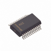
MAX1231BEEG+ Maxim Integrated Products, MAX1231BEEG+ Datasheet - Page 15

MAX1231BEEG+
Manufacturer Part Number
MAX1231BEEG+
Description
IC ADC 12BIT 300KSPS 24-QSOP
Manufacturer
Maxim Integrated Products
Datasheet
1.MAX1229BEEP.pdf
(22 pages)
Specifications of MAX1231BEEG+
Number Of Bits
12
Sampling Rate (per Second)
300k
Data Interface
MICROWIRE™, QSPI™, Serial, SPI™
Number Of Converters
1
Power Dissipation (max)
762mW
Voltage Supply Source
Single Supply
Operating Temperature
-40°C ~ 85°C
Mounting Type
Surface Mount
Package / Case
24-QSOP
Number Of Adc Inputs
16
Architecture
SAR
Conversion Rate
300 KSPs
Resolution
12 bit
Input Type
Differential
Interface Type
3-Wire (SPI, QSPI, MICROWIRE)
Voltage Reference
Internal 2.5 V or External
Supply Voltage (max)
3.3 V
Maximum Power Dissipation
762 mW
Maximum Operating Temperature
+ 85 C
Mounting Style
SMD/SMT
Minimum Operating Temperature
- 40 C
Lead Free Status / RoHS Status
Lead free / RoHS Compliant
The MAX1227/MAX1229/MAX1231 perform tempera-
ture measurements with an internal diode-connected
transistor. The diode bias current changes from 68µA
to 4µA to produce a temperature-dependent bias volt-
age difference. The second conversion result at 4µA is
subtracted from the first at 68µA to calculate a digital
value that is proportional to absolute temperature. The
output data appearing at DOUT is the above digital
code minus an offset to adjust from Kelvin to Celsius.
The reference voltage used for the temperature mea-
surements is derived from the internal reference source
to ensure that 1 LSB corresponds to 1/8 of a degree.
Table 5. Bipolar Mode Register (Addressed Through Setup Register)
Table 4. Unipolar Mode Register (Addressed Through Setup Register)
BIT NAME
BIT NAME
BCH10/11
BCH12/13
BCH14/15
UCH10/11
UCH12/13
UCH14/15
BCH0/1
BCH2/3
BCH4/5
BCH6/7
BCH8/9
UCH0/1
UCH2/3
UCH4/5
UCH6/7
UCH8/9
7 (MSB)
7 (MSB)
0 (LSB)
0 (LSB)
BIT
BIT
6
5
4
3
2
1
6
5
4
3
2
1
______________________________________________________________________________________
Temperature Measurements
Set to 1 to configure AIN0 and AIN1 for bipolar differential conversion.
Set to 1 to configure AIN2 and AIN3 for bipolar differential conversion.
Set to 1 to configure AIN4 and AIN5 for bipolar differential conversion.
Set to 1 to configure AIN6 and AIN7 for bipolar differential conversion.
Set to 1 to configure AIN8 and AIN9 for bipolar differential conversion (MAX1229/MAX1231 only).
Set to 1 to configure AIN10 and AIN11 for bipolar differential conversion (MAX1229/MAX1231 only).
Set to 1 to configure AIN12 and AIN13 for bipolar differential conversion (MAX1231 only).
Set to 1 to configure AIN14 and AIN15 for bipolar differential conversion (MAX1231only).
Set to 1 to configure AIN0 and AIN1 for unipolar differential conversion.
Set to 1 to configure AIN2 and AIN3 for unipolar differential conversion.
Set to 1 to configure AIN4 and AIN5 for unipolar differential conversion.
Set to 1 to configure AIN6 and AIN7 for unipolar differential conversion.
Set to 1 to configure AIN8 and AIN9 for unipolar differential conversion (MAX1229/MAX1231 only).
Set to 1 to configure AIN10 and AIN11 for unipolar differential conversion (MAX1229/MAX1231 only).
Set to 1 to configure AIN12 and AIN13 for unipolar differential conversion (MAX1231 only).
Set to 1 to configure AIN14 and AIN15 for unipolar differential conversion (MAX1231 only).
Temp Sensor, Internal Reference
12-Bit 300ksps ADCs with FIFO,
Figures 4–7 illustrate the conversion timing for the
MAX1227/MAX1229/MAX1231. The 12-bit conversion
result is output in MSB-first format with four leading
zeros. DIN data is latched into the serial interface on
the rising edge of SCLK. Data on DOUT transitions on
the falling edge of SCLK. Conversions in clock modes 00
and 01 are initiated by CNVST. Conversions in clock
modes 10 and 11 are initiated by writing an input data
byte to the conversion register. Data is binary for unipo-
lar mode and two’s complement for bipolar mode.
FUNCTION
FUNCTION
Output Data Format
15


