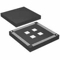
LTM2220IV-AA#PBF Linear Technology, LTM2220IV-AA#PBF Datasheet - Page 9

LTM2220IV-AA#PBF
Manufacturer Part Number
LTM2220IV-AA#PBF
Description
IC ADC 12BIT 170MSPS 100-SIPLGA
Manufacturer
Linear Technology
Datasheet
1.LTM2220IV-AAPBF.pdf
(12 pages)
Specifications of LTM2220IV-AA#PBF
Number Of Bits
12
Sampling Rate (per Second)
170M
Data Interface
Parallel
Number Of Converters
1
Power Dissipation (max)
1.05W
Voltage Supply Source
Single Supply
Operating Temperature
-40°C ~ 85°C
Mounting Type
Surface Mount
Package / Case
100-LGA
Lead Free Status / RoHS Status
Lead free / RoHS Compliant
Any noise present on the encode signal will result in ad-
ditional aperture jitter that will be RMS summed with the
inherent ADC aperture jitter.
In applications where jitter is critical (high input frequen-
cies) take the following into consideration:
1. Differential drive should be used.
2. Use as large an amplitude as possible; if transformer
coupled use a higher turns ratio to increase the ampli-
tude.
3. If the ADC is clocked with a sinusoidal signal, fi lter the
encode signal to reduce wideband noise.
4. Balance the capacitance and series resistance at both
encode inputs so that any coupled noise will appear at both
inputs as common mode noise. The clock inputs have a
common mode range of 1.1V to 2.5V. Each input may be
driven from ground to VDD for single-ended drive.
APPLICATIONS INFORMATION
CLOCK
INPUT
0.1µF
50Ω
Figure 3. Transformer Driven CLK+/CLK–
1:4
CLK+
CLK–
LTM2220-AA
V
V
DD
DD
1.6V BIAS
1.6V BIAS
6k
6k
V
DD
ADC CIRCUITS
TO INTERNAL
2220 F03
Maximum and Minimum Encode Rates
The maximum encode rate for the LTM2220-AA is 170Msps.
For the ADC to operate properly, the encode signal should
have a 50% (±20%) duty cycle. Each half cycle must have
at least 2ns for the ADC internal circuitry to have enough
settling time for proper operation.
If the clock is turned off for a long period of time, the duty
cycle stabilizer circuit will require one hundred clock cycles
for the PLL to lock onto the input clock.
The lower limit of the LTM2220-AA sample rate is de-
termined by droop of the sample-and-hold circuits. The
pipelined architecture of this ADC relies on storing analog
signals on small valued capacitors. Junction leakage will
discharge the capacitors. The specifi ed minimum operating
frequency for the LTM2220-AA is 1Msps.
Figure 5. CLK Drive Using a CMOS to PECL Translator
MC100LVELT22
V
THRESHOLD
Figure 4. Single-Ended CLK Drive,
Not Recommended for Low Jitter
D0
= 1.6V
3.3V
Q0
Q0
0.1µF
130Ω
83Ω
1.6V
LTM2220-AA
3.3V
CLK+
CLK–
CLK+
CLK–
130Ω
83Ω
LTM2220-AA
LTM2220-AA
2220 F04
2220 F05
2220aaf
9


