521633-2 TE Connectivity, 521633-2 Datasheet - Page 7
521633-2
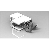
Manufacturer Part Number
521633-2
Description
250 ULTRA-POD FLAG 18-14 TPBR
Manufacturer
TE Connectivity
Specifications of 521633-2
Proprietary Name
Ultra-Pod
Receptacle Style
Flag
Mating Area Interface Dimensions (mm [in])
6.35 x 0.81 [.250 x .032]
Insulation Diameter (mm [in])
2.79-4.06 [.110-.160]
Insertion Force
Normal
Finish
Tin
Insulation Support
Insulation Support
Color
Natural
Fully Insulated
Yes
Wire Range (mm [awg])
0.80-2.00² [18-14], (2) 0.85-0.89; [(2) 20], (2) 0.80-0.90² [(2) 18]
Ul Flammability Rating
UL 94V-0
Housing Material
Nylon 6/6
Rohs/elv Compliance
RoHS compliant, ELV compliant
Lead Free Solder Processes
Not relevant for lead free process
Rohs/elv Compliance History
Always was RoHS compliant
Packaging Method
Strip


Rev D
(AW G)
W ire
Size
22
20
18
16
14
12
10
NOTE
(plain brass)
110
Tab Size
2
3
4
5
Heating
(a)
(b)
(c)
.250
.187
.110
Others
∆ temperature rise between 24 and 500 cycles shall not exceed 15°C on any conductor.
Alternating current to be used for temperature rise measurements, direct current to be
used for voltage drop measurements.
Total Voltage Drop = Crimp + Friction - EW L (equivalent wire length). These values are
for tin/tin or tin/brass receptacle to tab connections.
See Note (a)
Test Current
All
10
15
20
24
(am peres)
3
4
7
1st Insertion
Maxim um
Individual
110
10
10
4
6
8
8
8
Cycling
Others
All
14
20
30
40
48
Engaging/Disengaging Force.
6
8
Maxim um
Individual
17
20
14
.250
10
11
13
15
20
22
26
24 cycles
1st W ithdrawal
Figure 5
Figure 6
(m illivolts m axim um )
Test Voltage Drop
Minim um
Average
Others
Force (pounds)
See Note (b)
All
14
15
17
19
21
5
5
3
.250
Individual
Minim um
14
15
17
19
26
28
30
500 cycles
3
3
2
Others
All
18
19
21
23
25
Minim um
Average
6th W ithdrawal
4
3
2
m axim um
m axim um
Heating
initial.
30°C
45°C
final.
Tem perature Rise
Individual
Minim um
3
2
1
See Note (c)
m axim um
Cycling
85°C
108-1285
7 of 7
Related parts for 521633-2
Image
Part Number
Description
Manufacturer
Datasheet
Request
R

Part Number:
Description:
250 ULTRA-POD FLAG 18-14 BR
Manufacturer:
TE Connectivity
Datasheet:

Part Number:
Description:
Printers THERMAL PRINTER HS-SLEEVE MARKER
Manufacturer:
TE Connectivity


Part Number:
Description:
High Speed / Modular Connectors 30P HEADER ASSY
Manufacturer:
TE Connectivity
Datasheet:

Part Number:
Description:
High Speed / Modular Connectors REC 6X005P R/A LT B-PLANE HS3
Manufacturer:
TE Connectivity
Datasheet:

Part Number:
Description:
High Speed / Modular Connectors 2MM HM RCPT 50P R/A AU
Manufacturer:
TE Connectivity
Datasheet:

Part Number:
Description:
High Speed / Modular Connectors 2MM HM RCPT 50P R/A AU
Manufacturer:
TE Connectivity
Datasheet:


Part Number:
Description:
Manufacturer:
TE Connectivity
Datasheet:


Part Number:
Description:
Manufacturer:
TE Connectivity
Datasheet:

Part Number:
Description:
Manufacturer:
TE Connectivity
Datasheet:

Part Number:
Description:
Manufacturer:
TE Connectivity
Datasheet: