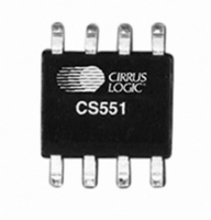
CS5510-ASZ Cirrus Logic Inc, CS5510-ASZ Datasheet - Page 17

CS5510-ASZ
Manufacturer Part Number
CS5510-ASZ
Description
IC ADC 16BIT EXTERNAL OSC 8-SOIC
Manufacturer
Cirrus Logic Inc
Datasheet
1.CS5513-BSZ.pdf
(26 pages)
Specifications of CS5510-ASZ
Number Of Converters
1
Package / Case
8-SOIC (0.200", 5.30mm Width)
Number Of Bits
16
Sampling Rate (per Second)
326
Data Interface
Serial
Power Dissipation (max)
1.9mW
Voltage Supply Source
Dual ±
Operating Temperature
-40°C ~ 85°C
Mounting Type
Surface Mount
Number Of Adc Inputs
1
Architecture
Delta-Sigma
Conversion Rate
16 SPs to 326 SPs
Resolution
16 bit
Input Type
Voltage
Interface Type
Serial
Voltage Reference
250 mV to 5 V
Maximum Power Dissipation
400 mW
Maximum Operating Temperature
+ 85 C
Mounting Style
SMD/SMT
Minimum Operating Temperature
- 40 C
Lead Free Status / RoHS Status
Lead free / RoHS Compliant
Lead Free Status / RoHS Status
Lead free / RoHS Compliant, Lead free / RoHS Compliant
Available stocks
Company
Part Number
Manufacturer
Quantity
Price
Part Number:
CS5510-ASZ
Manufacturer:
CIRRUS
Quantity:
20 000
2.5.3
As shown in Tables 1 and 2, the CS5510/11/12/13
present output conversions as 24-bit conversion
words. The first bit of the conversion word indi-
cates that a conversion is done through SDO fall-
ing from a logic high to a logic low level. The first
and the fourth bits output will always be zero. The
second and third bits are error flags, representing
an overflow or oscillation condition. In the
CS5510/11, there are four more bits of zero, and
the remaining 16 bits are the conversion data, out-
put MSB first (Table 2). In the CS5512/13, the final
DS337F4
Output Coding
S C L K
S C LK
S D O
S C L K
S D O
S D O
C S
C S
C S
Figure 17. Data Word Timing for the CS5511.
Figure 18. Data Word Timing for the CS5512.
Figure 19. Data Word Timing for the CS5513.
0
0
0
O F
O F
O F O D
O D
O D
0
0
0
M S B
M S B
0
D a ta T im e
D a ta T im e
D ata T im e
24 S C L K s
2 4 S C L K s
24 S C LK s
0
20 bits are the conversion data, which is output
MSB first (Table 1).
Bits D22-D21 are the two flag bits. The OF (Over-
range Flag) bit is set to a logic 1 any time the input
signal is more positive than positive full scale, or
more negative than negative full scale. It is cleared
back to logic 0 whenever a conversion word occurs
which is not overranged. The OD (Oscillation De-
tect) bit is set to a logic 1 any time that an oscillatory
condition is detected in the modulator. This does
not occur under normal operating conditions, but
may occur whenever the input to the converter is ex-
0
0
M S B
L S B
L S B
LS B
CS5510/11/12/13
0
0
0
0
0
0
17


