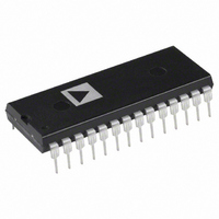
AD1674KNZ Analog Devices Inc, AD1674KNZ Datasheet

AD1674KNZ
Specifications of AD1674KNZ
Available stocks
Related parts for AD1674KNZ
AD1674KNZ Summary of contents
Page 1
LTR A Drawing updated to reflect current requirements REV SHEET REV SHEET REV STATUS REV OF SHEETS SHEET PMIC N/A PREPARED BY SANDRA ROONEY STANDARD CHECKED BY CHARLES E. BESORE ...
Page 2
SCOPE 1.1 Scope. This drawing documents two product assurance class levels consisting of high reliability (device classes Q and M) and space application (device class V). A choice of case outlines and lead finishes are available and are reflected ...
Page 3
Absolute maximum ratings. (unless otherwise specified digital common ............................................................................... +16 digital common ................................................................................ -16 LOGIC to digital common ......................................................................... +7 V Analog common to digital common ............................................................. ±1.0 V ...
Page 4
HANDBOOKS DEPARTMENT OF DEFENSE MIL-HDBK-103 - List of Standard Microcircuit Drawings. MIL-HDBK-780 - Standard Microcircuit Drawings. (Unless otherwise indicated, copies of the specification, standards, and handbooks are available from the Standardization Document Order Desk, 700 Robbins Avenue, Building 4D, Philadelphia, ...
Page 5
Test Symbol Power dissipation P D Input resistance R IN Internal reference 2/ V REF output voltage Logic input high voltage CE Logic input high voltage ...
Page 6
TABLE I. Electrical performance characteristics – Continued. Test Symbol Power supply rejection 4/ PSR Unipolar offset error V OSE Unipolar offset drift TC VOS Bipolar offset error B POE Bipolar offset drift TCB POE Full-scale calibration A B error A ...
Page 7
TABLE I. Electrical performance characteristics – Continued. Test Symbol Converter start timing section (see figure 4) Conversion time t C STS delay from CE t DSC CE pulse width t HEC setup SSC t CS low ...
Page 8
TABLE I. Electrical performance characteristics – Continued. Test Symbol Read timing full control mode section - continued (see figure setup SSR setup SRR setup t O SAR ...
Page 9
TABLE I. Electrical performance characteristics – Continued. 1/ Unless otherwise specified, T MIN to T MAX , +15 V ±10% or +12 V ±5%, V LOGIC = +5 V ±10 -15 V ±10% or ...
Page 10
STANDARD MICROCIRCUIT DRAWING DEFENSE SUPPLY CENTER COLUMBUS COLUMBUS, OHIO 43216-5000 DSCC FORM 2234 APR 97 Device type 01 Case outline X Terminal Terminal number symbol 1 V LOGIC 2 12 ...
Page 11
STANDARD MICROCIRCUIT DRAWING DEFENSE SUPPLY CENTER COLUMBUS COLUMBUS, OHIO 43216-5000 DSCC FORM 2234 APR 12 ...
Page 12
STANDARD MICROCIRCUIT DRAWING DEFENSE SUPPLY CENTER COLUMBUS COLUMBUS, OHIO 43216-5000 DSCC FORM 2234 APR 97 FIGURE 3. Functional block diagram. SIZE A REVISION LEVEL 5962-93164 SHEET A 12 ...
Page 13
STANDARD MICROCIRCUIT DRAWING DEFENSE SUPPLY CENTER COLUMBUS COLUMBUS, OHIO 43216-5000 DSCC FORM 2234 APR 97 FIGURE 4. Converter start timing diagram. SIZE A 5962-93164 REVISION LEVEL SHEET A 13 ...
Page 14
STANDARD MICROCIRCUIT DRAWING DEFENSE SUPPLY CENTER COLUMBUS COLUMBUS, OHIO 43216-5000 DSCC FORM 2234 APR 97 FIGURE 5. Read timing diagram. SIZE A REVISION LEVEL 5962-93164 SHEET A 14 ...
Page 15
FIGURE 6. Stand-alone mode timing low pulse for R/ C diagram. FIGURE 7. Stand-alone mode timing high pulse for R/ C diagram. STANDARD MICROCIRCUIT DRAWING DEFENSE SUPPLY CENTER COLUMBUS COLUMBUS, OHIO 43216-5000 DSCC FORM 2234 APR 97 __________________________________________ ___________________________________________ SIZE ...
Page 16
Access time high Z to logic low Float time logic high to high Z Access time high Z to logic high Float time logic low to high Z FIGURE 9. Load conditions for bus timing specifications. STANDARD MICROCIRCUIT DRAWING DEFENSE ...
Page 17
QUALITY ASSURANCE PROVISIONS 4.1 Sampling and inspection. For device classes Q and V, sampling and inspection procedures shall be in accordance with MIL-PRF-38535 or as modified in the device manufacturer's Quality Management (QM) plan. The modification in the QM ...
Page 18
Test requirements Interim electrical parameters (see 4.2) Final electrical parameters (see 4.2) Group A test requirements (see 4.4) Group C end-point electrical parameters (see 4.4) Group D end-point electrical parameters (see 4.4) Group E end-point electrical parameters (see 4.4) 1/ ...
Page 19
Group E inspection. Group E inspection is required only for parts intended to be marked as radiation hardness assured (see 3.5 herein). a. End-point electrical parameters shall be as specified in table II herein. b. For device classes Q ...
Page 20
STANDARD MICROCIRCUIT DRAWING BULLETIN Approved sources of supply for SMD 5962-93164 are listed below for immediate acquisition information only and shall be added to MIL-HDBK-103 and QML-38535 during the next revision. MIL-HDBK-103 and QML-38535 will be revised to include the ...


