HI1-574AKD-5 Intersil, HI1-574AKD-5 Datasheet - Page 18
HI1-574AKD-5
Manufacturer Part Number
HI1-574AKD-5
Description
IC ADC 12BIT 40KSPS 1CH 28-SBDIP
Manufacturer
Intersil
Datasheet
1.HI3-574AKN-5Z.pdf
(18 pages)
Specifications of HI1-574AKD-5
Number Of Bits
12
Sampling Rate (per Second)
40k
Data Interface
Parallel
Number Of Converters
1
Power Dissipation (max)
720mW
Voltage Supply Source
Dual ±
Operating Temperature
0°C ~ 75°C
Mounting Type
Through Hole
Package / Case
28-CDIP (0.600", 15.24mm)
Lead Free Status / RoHS Status
Lead free / RoHS Compliant
Available stocks
Company
Part Number
Manufacturer
Quantity
Price
Company:

Part Number:
HI1-574AKD-5
Manufacturer:
Intersil
Quantity:
352
Part Number:
HI1-574AKD-5
Manufacturer:
HAR
Quantity:
20 000


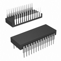
Dual-In-Line Plastic Packages (PDIP)
Intersil products are sold by description only. Intersil Corporation reserves the right to make changes in circuit design, software and/or specifications at any time without
notice. Accordingly, the reader is cautioned to verify that data sheets are current before placing orders. Information furnished by Intersil is believed to be accurate and
reliable. However, no responsibility is assumed by Intersil or its subsidiaries for its use; nor for any infringements of patents or other rights of third parties which may result
from its use. No license is granted by implication or otherwise under any patent or patent rights of Intersil or its subsidiaries.
SEATING
NOTES:
10. Corner leads (1, N, N/2 and N/2 + 1) for E8.3, E16.3, E18.3, E28.3,
INDEX
AREA
1. Controlling Dimensions: INCH. In case of conflict between English and
2. Dimensioning and tolerancing per ANSI Y14.5M-1982.
3. Symbols are defined in the “MO Series Symbol List” in Section 2.2 of
4. Dimensions A, A1 and L are measured with the package seated in
5. D, D1, and E1 dimensions do not include mold flash or protrusions.
6. E and
7. e
8. B1 maximum dimensions do not include dambar protrusions. Dambar
9. N is the maximum number of terminal positions.
PLANE
PLANE
BASE
Metric dimensions, the inch dimensions control.
Publication No. 95.
JEDEC seating plane gauge GS-3.
Mold flash or protrusions shall not exceed 0.010 inch (0.25mm).
ular to datum
e
protrusions shall not exceed 0.010 inch (0.25mm).
E42.6 will have a B1 dimension of 0.030 - 0.045 inch (0.76 - 1.14mm).
D1
B
B1
C
and e
must be zero or greater.
-A-
e
N
C
1 2 3
A
B
are measured at the lead tips with the leads unconstrained.
are measured with the leads constrained to be perpendic-
All Intersil U.S. products are manufactured, assembled and tested utilizing ISO9000 quality systems.
-C-
Intersil Corporation’s quality certifications can be viewed at www.intersil.com/design/quality
D
.
0.010 (0.25)
For information regarding Intersil Corporation and its products, see www.intersil.com
e
18
N/2
D1
M
-C-
E1
-B-
C A
A1
A2
B S
L
e
A
C
HI-574A, HI-674A
e
e
C L
E
A
C
B
E28.6
28 LEAD DUAL-IN-LINE PLASTIC PACKAGE
SYMBOL
A1
A2
B1
D1
E1
e
e
C
D
N
A
B
E
e
L
A
B
(JEDEC MS-011-AB ISSUE B)
0.015
0.125
0.014
0.030
0.008
1.380
0.005
0.600
0.485
0.115
MIN
-
-
0.100 BSC
0.600 BSC
INCHES
28
MAX
0.250
0.195
0.022
0.070
0.015
1.565
0.625
0.580
0.700
0.200
-
-
35.1
15.24
12.32
MILLIMETERS
0.39
3.18
0.356
0.77
0.204
0.13
2.93
MIN
-
-
15.24 BSC
2.54 BSC
28
39.7
15.87
14.73
17.78
MAX
6.35
4.95
0.558
1.77
0.381
5.08
-
-
Rev. 1 12/00
August 7, 2008
NOTES
FN3096.6
4
4
8
5
5
6
5
6
7
4
9
-
-
-
-
Related parts for HI1-574AKD-5
Image
Part Number
Description
Manufacturer
Datasheet
Request
R

Part Number:
Description:
HI1-303-5IC,ANALOG SWITCH,DUAL,SPDT,CMOS,DIP,14PIN
Manufacturer:
Intersil Corporation
Datasheet:

Part Number:
Description:
IC SWITCH DUAL SPDT 14CDIP
Manufacturer:
Intersil
Datasheet:
Part Number:
Description:
IC SWITCH DUAL SPDT 14CDIP
Manufacturer:
Intersil
Datasheet:

Part Number:
Description:
IC MULTIPLEXER 8X1 16CDIP
Manufacturer:
Intersil
Datasheet:
Part Number:
Description:
IC MULTIPLEXER 4X1 16CDIP
Manufacturer:
Intersil
Datasheet:
Part Number:
Description:
IC SWITCH DUAL SPDT 16CDIP
Manufacturer:
Intersil
Datasheet:

Part Number:
Description:
IC MULTIPLEXER DUAL 8X1 28CDIP
Manufacturer:
Intersil
Datasheet:
Part Number:
Description:
IC MULTIPLEXER DUAL 4X1 16CDIP
Manufacturer:
Intersil
Datasheet:
Part Number:
Description:
IC MULTIPLEXER 8X1 16CDIP
Manufacturer:
Intersil
Datasheet:

Part Number:
Description:
IC MULTIPLEXER 16X1 28CDIP
Manufacturer:
Intersil
Datasheet:

Part Number:
Description:
IC ADC 12BIT 40KSPS 1CH 28-SBDIP
Manufacturer:
Intersil
Datasheet:
Part Number:
Description:
IC ADC 12BIT 67KSPS 1CH 28-SBDIP
Manufacturer:
Intersil
Datasheet:

Part Number:
Description:
CONV D/A 12BIT 6.7MHZ 24-DIP
Manufacturer:
Intersil
Datasheet:
Part Number:
Description:
IC SWITCH QUAD SPST 16CDIP
Manufacturer:
Intersil
Datasheet:
Part Number:
Description:
IC MULTIPLEXER 8X1 16CDIP
Manufacturer:
Intersil
Datasheet: