MAX152CAP+ Maxim Integrated Products, MAX152CAP+ Datasheet
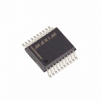
IC ADC 8BIT 1UA PWR-DWN 20-SSOP

MAX152CAP+

Manufacturer Part Number
MAX152CAP+
Description
IC ADC 8BIT 1UA PWR-DWN 20-SSOP
Manufacturer
Maxim Integrated Products
Datasheet

Specifications of MAX152CAP+

Number Of Bits
8
Sampling Rate (per Second)
400k
Data Interface
Parallel
Number Of Converters
3
Power Dissipation (max)
640mW
Voltage Supply Source
Dual ±
Operating Temperature
0°C ~ 70°C
Mounting Type
Surface Mount
Package / Case
20-SSOP
Lead Free Status / RoHS Status
Lead free / RoHS Compliant
The MAX152 high-speed, microprocessor (µP)-com-
patible, 8-bit analog-to-digital converter (ADC) uses a
half-flash technique to achieve a 1.8µs conversion
time, and digitizes at a rate of 400k samples per sec-
ond (ksps). It operates with single +3V or dual ±3V
supplies and accepts either unipolar or bipolar inputs.
A
a typical value of 1µA. The part returns from power-
down and acquires an input signal in less than 900ns,
providing large reductions in supply current in applica-
tions with burst-mode input signals.
The MAX152 is DC and dynamically tested. Its µP inter-
face appears as a memory location or input/output port that
requires no external interface logic. The data outputs use
latched, three-state buffered circuitry for direct connection
to a µP data bus or system input port. The ADC's input/ref-
erence arrangement enables ratiometric operation. A fully-
assembled evaluation kit provides a proven PC board lay-
out to speed prototyping and design.
19-0119; Rev. 1; 12/93
________________Functional Diagram
Call toll free 1-800-998-8800 for free samples or literature.
_______________General Description
_______________________Applications
P
VREF+
VREF-
O
V IN
W
Cellular Telephones
Portable Radios
Battery-Powered Systems
Burst-Mode Data Acquisition
Digital Signal Processing
Telecommunications
High-Speed Servo Loops
12
11
E
1
R
D
GND
O
W
10
VREF+
TIMING AND CONTROL CIRCUITRY
N
16
MODE
________________________________________________________________ Maxim Integrated Products
pin reduces current consumption to
7
FLASH
(4LSB)
4-BIT
FLASH
4-BIT
DAC
ADC
4-BIT
WR/RDY CS
ADC
6
+3V, 8-Bit ADC with 1µA Power-Down
13
RD
8
INT
9
MAX152
V SS
DRIVERS
THREE-
V DD
STATE
19
20
18
PWRDN
D0-D7
DATA
OUT
PINS
2-5,
14-17
* Contact factory for dice specifications.
** Contact factory for availability and processing to MIL-STD-883.
__________________Pin Configuration
______________Ordering Information
___________________________Features
MAX152CPP
MAX152CWP
MAX152CAP
MAX152C/D
MAX152EPP
MAX152EWP
MAX152EAP
MAX152MJP
Single +3.0V to +3.6V Supply
1.8µs Conversion Time
Power-Up in 900ns
Internal Track/Hold
400ksps Throughput
Low Power: 1.5mA (Operating Mode)
300kHz Full-Power Bandwidth
20-Pin DIP, SO and SSOP Packages
No External Clock Required
Unipolar/Bipolar Inputs
Ratiometric Reference Inputs
2.7V Version Available – Contact Factory
PART
TOP VIEW
D0 (LSB)
WR/RDY
MODE
GND
V IN
INT
1µA
RD
D1
D2
D3
10
-40°C to +85°C
-40°C to +85°C
-40°C to +85°C
-55°C to +125°C
1
2
3
4
5
6
7
8
9
TEMP. RANGE
0°C to +70°C
0°C to +70°C
0°C to +70°C
0°C to +70°C
DIP/SO/SSOP
(Power-Down Mode)
MAX152
20
19
18
17
16
15
14
13
12
11
V DD
V SS
PWRDN
D7 (MSB)
D6
D5
D4
CS
VREF+
VREF-
20 Plastic DIP
20 Wide SO
20 SSOP
Dice*
20 Plastic DIP
20 Wide SO
20 SSOP
20 CERDIP**
PIN-PACKAGE
1

Related parts for MAX152CAP+

MAX152CAP+ Summary of contents

Page 1

... WR/RDY CS GND MODE RD INT ________________________________________________________________ Maxim Integrated Products Call toll free 1-800-998-8800 for free samples or literature. ___________________________Features Single +3.0V to +3.6V Supply 1.8µs Conversion Time Power-Up in 900ns Internal Track/Hold 400ksps Throughput Low Power: 1.5mA (Operating Mode) 300kHz Full-Power Bandwidth 20-Pin DIP, SO and SSOP Packages ...

Page 2

ADC with 1µA Power-Down ABSOLUTE MAXIMUM RATINGS GND .............................................................-0. GND ..............................................................+0.3V to -7V Digital Input Voltage to GND ........................-0.3V 0.3V) Digital Output Voltage to GND .....................-0.3V, (V ...

Page 3

ADC with 1µA Power-Down ELECTRICAL CHARACTERISTICS (continued) (Unipolar input range 3.0V to 3.6V, GND = 0V mode (pin 7 = GND unless otherwise noted.) A MIN MAX PARAMETER ...

Page 4

ADC with 1µA Power-Down TIMING CHARACTERISTICS (Unipolar input range 3V 0V PARAMETER SYMBOL CONDITIONS t < t Conversion Time RD INTL t CWR C = 100pF (WR-RD Mode) L Conversion Time ...

Page 5

ADC with 1µA Power-Down __________________________________________Typical Operating Characteristics (T =+25°C, unless otherwise noted). A CONVERSION TIME vs. AMBIENT TEMPERATURE 1.6 1.4 1 3. 3. 3.0V DD 0.6 0.4 -60 ...

Page 6

ADC with 1µA Power-Down V DD DATA DATA OUTPUTS OUTPUTS HIGH HIGH Figure 1. Load Circuits for Data-Access Time Test ____________________Pin Description PIN NAME FUNCTION Analog Input. ...

Page 7

ADC with 1µA Power-Down Once the MAX152 is in power-down mode, lowest sup- ply current is drawn with MODE low (RD mode) due to an internal pull-down resistor at this pin. In addition, for minimum current consumption, other ...

Page 8

ADC with 1µA Power-Down IHWR INT t INTL OLD DATA NEW DATA D0- Figure 6. Stand-Alone Mode Timing ( = A minimum acquisition time ( required from ...

Page 9

ADC with 1µA Power-Down ____________Analog Considerations Figures 7a-7c show some reference connections. VREF+ and VREF- inputs set the full-scale and zero- input voltages of the ADC. The voltage at VREF- defines the input that produces an output code ...

Page 10

ADC with 1µA Power-Down Conversion Rate The maximum sampling rate (f ) for the MAX152 is max achieved in the WR-RD mode (t < culated as follows max ...

Page 11

ADC with 1µA Power-Down ___________________Chip Topography MAX152 WR/RDY MODE RD INT GND VREF- VREF+ 0.098" 2.49mm TRANSISTOR COUNT: 1856 SUBSTRATE CONNECTED ________________________________________________________Package Information D1 D ...

Page 12

ADC with 1µA Power-Down __________________________________________Package Information (continued ______________________________________________________________________________________ h x 45˚ 0.127mm 0.004in INCHES MILLIMETERS DIM MIN MAX MIN MAX A 0.093 0.104 2.35 2.65 A1 0.004 0.012 ...

Related keywords