AR1020-I/ML Microchip Technology, AR1020-I/ML Datasheet - Page 26
AR1020-I/ML
Manufacturer Part Number
AR1020-I/ML
Description
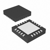
IC TOUCH SCREEN CTRLR 20-QFN
Manufacturer
Microchip Technology
Type
Resistiver
Specifications of AR1020-I/ML
Resolution (bits)
10 b
Touch Panel Interface
4-Wire, 5-Wire, 8-Wire
Number Of Inputs/keys
3 Key
Data Interface
I²C, Serial, SPI™
Voltage - Supply
3.3 V ~ 5.5 V
Current - Supply
17mA
Operating Temperature
-40°C ~ 85°C
Mounting Type
Surface Mount
Package / Case
20-VQFN Exposed Pad, 20-HVQFN, 20-SQFN, 20-DHVQFN
Voltage Supply Source
Single Supply
Controller Type
Touch Screen
Ic Interface Type
I2C, SPI
Supply Voltage Range
3.3V To 5V
Operating Temperature Range
-40°C To +85°C
Digital Ic Case Style
QFN
No. Of Pins
20
Lead Free Status / RoHS Status
Lead free / RoHS Compliant
Sampling Rate (per Second)
-
Lead Free Status / RoHS Status
Lead free / RoHS Compliant, Lead free / RoHS Compliant
Available stocks
Company
Part Number
Manufacturer
Quantity
Price
Company:

Part Number:
AR1020-I/ML
Manufacturer:
MICROCHIP
Quantity:
3 400
Company:
Part Number:
AR1020-I/ML
Manufacturer:
MCP
Quantity:
5 056
Part Number:
AR1020-I/ML
Manufacturer:
MIC
Quantity:
20 000


7.15.8 EEPROM Read - 0x28
The controller has 256 bytes of on-board EEPROM.
This command provides a means to read values from the EEPROM.
Send
Receive : <0x55><0x02 + # EEPROM Read><Response><0x28><EEPROM value>…<EEPROM value>
7.15.9 EEPROM Write - 0x29
The controller has 256 bytes of on-board EEPROM.
This command provides a means to write values to the EEPROM.
Write to EEPROM as follows.
Send: <0x55><0x04 + # EEPROM to Write><0x29><EEPROM Address High byte><EEPROM Address Low byte>
Receive : <0x55><0x02><Response><0x29>
7.15.10 EEPROM Write to Registers - 0x2B
Write applicable EEPROM data to Configuration Registers. This will cause the controller to immediately begin
using changes made to EEPROM stored Configuration Register values. A power cycle of the controller will
automatically cause the controller to use changes made to the EEPROM stored Configuration Register values,
without the need for issuing this command. This command eliminates the need for the power cycle.
Send
Receive : <0x55><0x02><Response><0x2B>
DS41393A-Page 22
Warning: ONLY write to user EEPROM addresses of 0x80–0xFF.
One of the following actions is required for EEPROM changes to be used by the controller.
The first 128 bytes (address range 0x00–0x7F) are reserved by the controller for the configuration register
settings and calibration data.
The second 128 bytes (address range 0x80–0xFF) are provided for the user’s application, if desired.
The first 128 bytes (address range 0x00–0x7F) are reserved by the controller for the configuration register
settings and calibration data.
The second 128 bytes (address range 0x80–0xFF) are provided for the user’s application, if desired.
The controller power must be cycled from OFF to ON
or
Issue the “EEPROM Write to Registers” command
: <0x55><0x04><0x28><EEPROM Address High byte><EEPROM Address Low byte><# of EEPROM to Read>
# of EEPROM to Read
EEPROM Address High byte : 0x00
<# of EEPROM to Write><Data>…<Data>
# of EEPROM to Write
EEPROM Address High byte : 0x00
: <0x55><0x01><0x2B>
: 0x01 thru 0x08
: 0x01 thru 0x08
© 2009 Microchip Technology, Inc.
Related parts for AR1020-I/ML
Image
Part Number
Description
Manufacturer
Datasheet
Request
R

Part Number:
Description:
IC TOUCH SCREEN CTRLR 20-SSOP
Manufacturer:
Microchip Technology
Datasheet:

Part Number:
Description:
IC TOUCH SCREEN CTRLR 20-SOIC
Manufacturer:
Microchip Technology
Datasheet:

Part Number:
Description:
Regulator; Modular; M5 Rc(PT) ports; name plate; gauge in imperial units
Manufacturer:
SMC Corporation
Datasheet:
Part Number:
Description:
AIR REGULATOR, M5 PORT, PANEL MT W/SET NUT, .02-.2MPA SETTING, PSI, F
Manufacturer:
SMC Corporation
Datasheet:

Part Number:
Description:
Manufacturer:
Microchip Technology Inc.
Datasheet:
Part Number:
Description:
Manufacturer:
Microchip Technology Inc.
Datasheet:
Part Number:
Description:
Manufacturer:
Microchip Technology Inc.
Datasheet:
Part Number:
Description:
Manufacturer:
Microchip Technology Inc.
Datasheet:
Part Number:
Description:
Manufacturer:
Microchip Technology Inc.
Datasheet:
Part Number:
Description:
Manufacturer:
Microchip Technology Inc.
Datasheet:
Part Number:
Description:
Manufacturer:
Microchip Technology Inc.
Datasheet: