AR1020-I/ML Microchip Technology, AR1020-I/ML Datasheet - Page 29
AR1020-I/ML
Manufacturer Part Number
AR1020-I/ML
Description
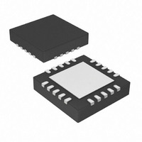
IC TOUCH SCREEN CTRLR 20-QFN
Manufacturer
Microchip Technology
Type
Resistiver
Specifications of AR1020-I/ML
Resolution (bits)
10 b
Touch Panel Interface
4-Wire, 5-Wire, 8-Wire
Number Of Inputs/keys
3 Key
Data Interface
I²C, Serial, SPI™
Voltage - Supply
3.3 V ~ 5.5 V
Current - Supply
17mA
Operating Temperature
-40°C ~ 85°C
Mounting Type
Surface Mount
Package / Case
20-VQFN Exposed Pad, 20-HVQFN, 20-SQFN, 20-DHVQFN
Voltage Supply Source
Single Supply
Controller Type
Touch Screen
Ic Interface Type
I2C, SPI
Supply Voltage Range
3.3V To 5V
Operating Temperature Range
-40°C To +85°C
Digital Ic Case Style
QFN
No. Of Pins
20
Lead Free Status / RoHS Status
Lead free / RoHS Compliant
Sampling Rate (per Second)
-
Lead Free Status / RoHS Status
Lead free / RoHS Compliant, Lead free / RoHS Compliant
Available stocks
Company
Part Number
Manufacturer
Quantity
Price
Company:

Part Number:
AR1020-I/ML
Manufacturer:
MICROCHIP
Quantity:
3 400
Company:
Part Number:
AR1020-I/ML
Manufacturer:
MCP
Quantity:
5 056
Part Number:
AR1020-I/ML
Manufacturer:
MIC
Quantity:
20 000


8 BASICS OF RESISTIVE SENSORS
8.1 Terminology
ITO (Indium Tin Oxide) is the resistive coating that makes up the active area of the touch sensor. ITO is a
transparent semiconductor that is sputtered onto the touch sensor layers.
Flex or Film or Topsheet is the top sensor layer that a user touches. Flex refers to the fact that the top layer
physically flexes from the pressure of a touch.
Stable or Glass is the bottom sensor layer that interfaces against the display.
Spacer Adhesive is a frame of adhesive that connects the Flex and Stable layers together around the perimeter.
Spacer Dots maintain physical and electrical separation between the Flex and Stable layers. The dots are
typically printed onto the Stable layer.
Bus Bars or Silver Frit electrically connect to the ITO on the Flex and Stable layers to the sensor’s interface tail.
Bus bars are typically screen printed silver ink. They are usually much lower in resistivity than the ITO.
X-Axis is the left and right direction on the touch sensor.
Y-Axis is the top and bottom direction on the touch sensor.
Drive Lines supply a voltage gradient across the sensor.
8.2 General
Resistive 4, 5, and 8-wire touch sensors consist of two facing conductive layers, held in physical separation from
each other. The force of a touch causes the top layer to move and make electrical contact with the bottom layer.
Touch position measurements are typically made by applying a linear voltage gradient across a layer or axis of
the touch sensor. The touch position voltage for the axis can be measured using the opposing layer.
A comparison of typical sensor constructions is shown below.
© 2009 Microchip Technology, Inc.
4 Wire
5 Wire
8 Wire
Table 10 : Sensor Comparison
Sensor
Less expensive than 5-wire or 8-wire
Lower power than 5-wire
More linear (without correction) than 5-wire
Touch inaccuracies occur from flex layer damage or resistance changes
Maintains touch accuracy with flex layer damage
Inherent non-linearity often requires touch data correction
Touch inaccuracies occur from resistance changes
More expensive than 4 wire
Lower power than 5 wire
More linear (without correction) than 5-wire
Touch inaccuracies occur from flex layer damaged
Maintains touch accuracy with resistance changes
Comments
DS41393A-Page 25
Related parts for AR1020-I/ML
Image
Part Number
Description
Manufacturer
Datasheet
Request
R

Part Number:
Description:
IC TOUCH SCREEN CTRLR 20-SSOP
Manufacturer:
Microchip Technology
Datasheet:

Part Number:
Description:
IC TOUCH SCREEN CTRLR 20-SOIC
Manufacturer:
Microchip Technology
Datasheet:

Part Number:
Description:
Regulator; Modular; M5 Rc(PT) ports; name plate; gauge in imperial units
Manufacturer:
SMC Corporation
Datasheet:
Part Number:
Description:
AIR REGULATOR, M5 PORT, PANEL MT W/SET NUT, .02-.2MPA SETTING, PSI, F
Manufacturer:
SMC Corporation
Datasheet:

Part Number:
Description:
Manufacturer:
Microchip Technology Inc.
Datasheet:
Part Number:
Description:
Manufacturer:
Microchip Technology Inc.
Datasheet:
Part Number:
Description:
Manufacturer:
Microchip Technology Inc.
Datasheet:
Part Number:
Description:
Manufacturer:
Microchip Technology Inc.
Datasheet:
Part Number:
Description:
Manufacturer:
Microchip Technology Inc.
Datasheet:
Part Number:
Description:
Manufacturer:
Microchip Technology Inc.
Datasheet:
Part Number:
Description:
Manufacturer:
Microchip Technology Inc.
Datasheet: