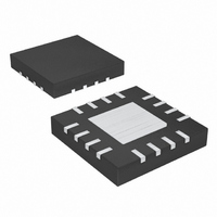
MAX5496ETE+ Maxim Integrated Products, MAX5496ETE+ Datasheet - Page 15

MAX5496ETE+
Manufacturer Part Number
MAX5496ETE+
Description
IC DGTL POT 10BIT 16-TQFN-EP
Manufacturer
Maxim Integrated Products
Datasheet
1.MAX5494ETE.pdf
(20 pages)
Specifications of MAX5496ETE+
Taps
1024
Resistance (ohms)
10K
Number Of Circuits
2
Temperature Coefficient
35 ppm/°C Typical
Memory Type
Non-Volatile
Interface
3-Wire Serial
Voltage - Supply
2.5 V ~ 5.25 V
Operating Temperature
-40°C ~ 85°C
Mounting Type
Surface Mount
Package / Case
16-TQFN Exposed Pad
Resistance In Ohms
10K
Number Of Pots
Dual
Taps Per Pot
1024
Resistance
10 KOhms
Wiper Memory
Non Volatile
Digital Interface
Serial (3-Wire, SPI)
Operating Supply Voltage
2.7 V to 5.25 V
Supply Current
1.5 uA
Maximum Operating Temperature
+ 85 C
Minimum Operating Temperature
- 40 C
Description/function
1024-Tap Dual 10k Nonvolatile Linear-Taper Digital Potentiometer (Variable Resistor)
Mounting Style
SMD/SMT
Supply Voltage (max)
5.25 V
Supply Voltage (min)
2.7 V
Tolerance
25 %
Lead Free Status / RoHS Status
Lead free / RoHS Compliant
The “write wiper register” command writes data to the
volatile random access memory (RAM), leaving the NV
registers unchanged. When the device powers up, the
data stored in the NV registers transfers to the wiper
register, moving the wiper to the stored position. Figure
8 shows how to write data to wiper register 1.
The “write NV register” command (C1, C0 = 01) stores
the position of the wiper to the NV registers for use at
power-up. Alternatively, the “copy wiper register to NV
register” command writes to the NV register. Writing to
Figure 8. Write Wiper Register 1
Figure 9. Write NV Register 1
ACTION
SCLK
ACTION
DIN
CS
SCLK
DIN
CS
0
1
0
1
0
2
______________________________________________________________________________________
0
C1 C0
2
0
3
C1 C0
0
3
1
10-Bit, Dual, Nonvolatile, Linear-Taper
4
0
4
0
5
0
5
0
6
0
RA1 RA0
6
0
7
RA1 RA0
0
7
1
Write NV Register
8
1
8
D9 D8 D7 D6 D5 D4 D3 D2
9
D9 D8 D7 D6 D5 D4 D3 D2
9
10
10
11 12 13 14
11 12 13 14
the NV register does not affect the position of the
wipers. The operation takes up to 12ms (max) after CS
goes high to complete and no other operation should
be performed until completion. Figure 9 shows how to
write data to the NV register 1.
The “copy wiper register to NV register” command (C1,
C0 = 10) stores the current position of the wiper to the
NV register for use at power-up. Figure 10 shows how
to copy data from wiper register 1 to NV register 1.
Digital Potentiometers
15
15
16
16
D1 D0
17
D1 D0
17
18
Copy Wiper Register to NV Register
18
X
19 20 21 22
X
19 20 21 22
X
X
X
X
X
X
X
23 24
X
23 24
X
X
(DEVICE IS BUSY)
REGISTER 1
REGISTER 1
WRITE NV
UPDATED
WIPER
t
BUSY
15


