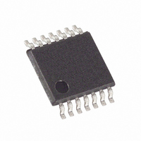
DS1807E+ Maxim Integrated Products, DS1807E+ Datasheet - Page 4

DS1807E+
Manufacturer Part Number
DS1807E+
Description
IC POT ADDRESS 2X AUDIO 14-TSSOP
Manufacturer
Maxim Integrated Products
Datasheet
1.DS1807S.pdf
(13 pages)
Specifications of DS1807E+
Taps
64 + Mute
Resistance (ohms)
45K
Number Of Circuits
2
Temperature Coefficient
750 ppm/°C Typical
Memory Type
Volatile
Interface
I²C, 2-Wire Serial
Voltage - Supply
2.7 V ~ 5.5 V
Operating Temperature
-40°C ~ 85°C
Mounting Type
Surface Mount
Package / Case
14-TSSOP
Resistance In Ohms
45K
Number Of Pots
Dual
Taps Per Pot
64
Resistance
45 KOhms
Wiper Memory
Volatile
Digital Interface
Serial (2-Wire)
Operating Supply Voltage
2.7 V to 5.5 V
Supply Current
40 uA
Maximum Operating Temperature
+ 85 C
Minimum Operating Temperature
- 40 C
Mounting Style
SMD/SMT
Supply Voltage (max)
5.5 V
Supply Voltage (min)
2.7 V
Tolerance
20 %
Lead Free Status / RoHS Status
Lead free / RoHS Compliant
DS1807
DS1807 ATTENUATOR CONFIGURATION Figure 3
ZERO-CROSSING DETECTION
The DS1807 provides many features for digitally controlled audio applications. Zero-crossing detection is
useful in eliminating “zipper noise,” which is commonly associated with digital potentiometers. Zipper
noise (because it sounds like a zipper) is caused by discrete wiper position changes on the resistor array.
These changes cause discontinuities in the audio output signal which are manifested as audible pops
heard at the output of the audio chain. If subsequent amplification follows the digital potentiometer, this
audible noise can be quite disturbing. The DS1807 minimizes zipper noise by allowing wiper position
changes only during zero-crossings of the input signal.
The zero-crossing detection feature can be enabled or disabled via software. The complete software
command for enabling or disabling zero-crossing is discussed in the section, “2-wire serial data bus.”
When enabled, the zero-crossing detection feature allows independent wiper changes within a 50
millisecond time window when the Hx and Lx (where x = 0 or 1) terminals have equal potentials. The 50
millisecond time window begins once the DS1807 has responded with an ACKNOWLEDGE after a
“write potentiometer “ command. The STOP condition is discussed in the following section.
If at 50 milliseconds the DS1807 has not detected a zero-crossing (Hx - Lx = 0), the wiper position of the
potentiometer(s) will change regardless of the state of the input signal.
When the zero-crossing detection feature is not activated, the DS1807 will allow movement to the new
wiper position as soon as the ACKNOWLEDGE condition has been issued by the master controlling
device.
The DS1807 is designed to provide the zero-crossing detection feature when initially powered. If this
feature is not to be used, it must be deactivated once the device has reached a fully powered condition.
2-WIRE SERIAL DATA BUS
The DS1807 supports a bi-directional 2-wire bus and data transmission protocol. A device that sends data
on the bus is defined as a transmitter, and a device receiving data as a receiver. The device that controls
the message is called a “master.” The devices that are controlled by the master are “slaves.” The bus must
be controlled by a master device which generates the serial clock (SCL), controls the bus access, and
generates the START and STOP conditions. The DS1807 operates as a slave on the 2-wire bus.
Connections to the bus are made via the open-drain I/O line, SDA, and the serial clock line, SCL.
The following bus protocol has been defined (See Figure 4).
§ Data transfer may be initiated only when the bus is not busy.
§ During data transfer, the data line must remain stable whenever the clock line is HIGH. Changes in
the data line while the clock line is high will be interpreted as control signals.
4 of 13
110499


