MCP4018T-103E/LT Microchip Technology, MCP4018T-103E/LT Datasheet - Page 35
MCP4018T-103E/LT
Manufacturer Part Number
MCP4018T-103E/LT
Description
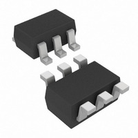
IC DGTL POT 10K 128TAPS SC70-6
Manufacturer
Microchip Technology
Datasheet
1.MCP4018T-502ELT.pdf
(66 pages)
Specifications of MCP4018T-103E/LT
Package / Case
SC-70-6, SC-88, SOT-363
Temperature Coefficient
150 ppm/°C Typical
Taps
128
Resistance (ohms)
10K
Number Of Circuits
1
Memory Type
Volatile
Interface
I²C, 2-Wire Serial
Voltage - Supply
1.8 V ~ 5.5 V
Operating Temperature
-40°C ~ 125°C
Mounting Type
Surface Mount
Resistance In Ohms
10K
Number Of Pots
Single
Taps Per Pot
128
Resistance
10 KOhms
Wiper Memory
Volatile
Buffered Wiper
Buffered
Digital Interface
Serial (2-Wire, I2C)
Operating Supply Voltage
2.5 V or 3.3 V or 5 V
Supply Current
0.045 mA (Typ)
Maximum Operating Temperature
+ 125 C
Minimum Operating Temperature
- 40 C
Description/function
7 Bit Single I2C Digital Potentiometer
Mounting Style
SMD/SMT
Supply Voltage (max)
5.5 V
Supply Voltage (min)
1.8 V
Tolerance
20 %
Lead Free Status / RoHS Status
Lead free / RoHS Compliant
Lead Free Status / RoHS Status
Lead free / RoHS Compliant, Lead free / RoHS Compliant
Other names
MCP4018T-103E/LTTR
Available stocks
Company
Part Number
Manufacturer
Quantity
Price
Company:

Part Number:
MCP4018T-103E/LT
Manufacturer:
MICROCHIP
Quantity:
12 000
Part Number:
MCP4018T-103E/LT
Manufacturer:
MICROCHIP/微芯
Quantity:
20 000


5.2.5
The Stop bit (see
I
the SDA signal rising when the SCL signal is “High”.
A Stop bit resets the I
FIGURE 5-6:
Transmit Mode.
5.2.6
“Clock Stretching” is something that the Secondary
Device can do, to allow additional time to “respond” to
the “data” that has been received.
The MCP4017/18/19 will not strech the clock signal
(SCL) since memory read accesses occur fast enough.
FIGURE 5-7:
FIGURE 5-8:
© 2009 Microchip Technology Inc.
2
C Data Transfer Sequence. The Stop bit is defined as
SDA A / A
SCL
SDA
SCL
SDA
SCL
S
STOP BIT
CLOCK STRETCHING
Figure
1st
Bit Bit
2
Condition
C interface of the other devices.
Stop Condition Receive or
Typical 16-bit I
I
START
2
2nd 3rd 4th 5th 6th 7th 8th
C Data States and Bit Sequence.
5-6) Indicates the end of the
Bit Bit Bit Bit Bit Bit
Data allowed
to change
2
C Waveform Format.
P
Data or
A valid
A/A
1st 2nd 3rd 4th 5th 6th 7th 8th A/A
Bit Bit
5.2.7
If any part of the I
command format, it is aborted. This can be intentionally
accomplished with a START or STOP condition. This is
done so that noisy transmissions (usually an extra
START or STOP condition) are aborted before they
corrupt the device.
5.2.8
The MCP4017/18/19 expects to receive entire, valid
I
defined as a valid command is due to a bus corruption
and will enter a passive high condition on the SDA
signal. All signals will be ignored until the next valid
START condition and CONTROL BYTE are received.
2
C commands and will assume any command not
Bit Bit Bit Bit Bit
ABORTING A TRANSMISSION
IGNORING AN I
AND “FALLING OFF” THE BUS
MCP4017/18/19
2
C transmission does not meet the
Condition
STOP
2
Bit
C TRANSMISSION
DS22147A-page 35
P
Related parts for MCP4018T-103E/LT
Image
Part Number
Description
Manufacturer
Datasheet
Request
R

Part Number:
Description:
IC DGTL POT 5K 128TAPS SC70-6
Manufacturer:
Microchip Technology
Datasheet:
Part Number:
Description:
IC DGTL POT 50K 128TAPS SC70-6
Manufacturer:
Microchip Technology
Datasheet:
Part Number:
Description:
IC DGTL POT 100K 128TAPS SC70-6
Manufacturer:
Microchip Technology
Datasheet:

Part Number:
Description:
7-Bit Single I2C� Digital POT with Volatile Memory in SC70
Manufacturer:
MICROCHIP [Microchip Technology]
Datasheet:

Part Number:
Description:
Manufacturer:
Microchip Technology Inc.
Datasheet:
Part Number:
Description:
Manufacturer:
Microchip Technology Inc.
Datasheet:
Part Number:
Description:
Manufacturer:
Microchip Technology Inc.
Datasheet:
Part Number:
Description:
Manufacturer:
Microchip Technology Inc.
Datasheet:
Part Number:
Description:
Manufacturer:
Microchip Technology Inc.
Datasheet:
Part Number:
Description:
Manufacturer:
Microchip Technology Inc.
Datasheet:
Part Number:
Description:
Manufacturer:
Microchip Technology Inc.
Datasheet: