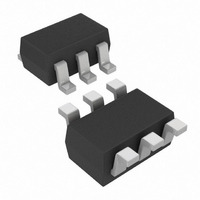
MCP4018T-103E/LT Microchip Technology, MCP4018T-103E/LT Datasheet - Page 36

MCP4018T-103E/LT
Manufacturer Part Number
MCP4018T-103E/LT
Description
IC DGTL POT 10K 128TAPS SC70-6
Manufacturer
Microchip Technology
Datasheet
1.MCP4018T-502ELT.pdf
(66 pages)
Specifications of MCP4018T-103E/LT
Package / Case
SC-70-6, SC-88, SOT-363
Temperature Coefficient
150 ppm/°C Typical
Taps
128
Resistance (ohms)
10K
Number Of Circuits
1
Memory Type
Volatile
Interface
I²C, 2-Wire Serial
Voltage - Supply
1.8 V ~ 5.5 V
Operating Temperature
-40°C ~ 125°C
Mounting Type
Surface Mount
Resistance In Ohms
10K
Number Of Pots
Single
Taps Per Pot
128
Resistance
10 KOhms
Wiper Memory
Volatile
Buffered Wiper
Buffered
Digital Interface
Serial (2-Wire, I2C)
Operating Supply Voltage
2.5 V or 3.3 V or 5 V
Supply Current
0.045 mA (Typ)
Maximum Operating Temperature
+ 125 C
Minimum Operating Temperature
- 40 C
Description/function
7 Bit Single I2C Digital Potentiometer
Mounting Style
SMD/SMT
Supply Voltage (max)
5.5 V
Supply Voltage (min)
1.8 V
Tolerance
20 %
Lead Free Status / RoHS Status
Lead free / RoHS Compliant
Lead Free Status / RoHS Status
Lead free / RoHS Compliant, Lead free / RoHS Compliant
Other names
MCP4018T-103E/LTTR
Available stocks
Company
Part Number
Manufacturer
Quantity
Price
Company:
Part Number:
MCP4018T-103E/LT
Manufacturer:
MICROCHIP
Quantity:
12 000
Part Number:
MCP4018T-103E/LT
Manufacturer:
MICROCHIP/微芯
Quantity:
20 000
MCP4017/18/19
5.2.9
The MCP4017/18/19 is a slave I
supports 7-bit slave addressing. The slave address
contains seven fixed bits.
byte format.
5.2.9.1
The Control Byte is always preceded by a START
condition. The Control Byte contains the slave address
consisting of seven fixed bits and the R/W bit.
9
the I
FIGURE 5-9:
I
FIGURE 5-10:
DS22147A-page 36
2
Start
bit
A = 0 = Slave Device Acknowledges byte
A = 1 = Slave Device does not Acknowledge byte
A bit (controlled by slave device)
S A6 A5 A4 A3 A2 A1 A0 R/W A/A
C Control Byte.
shows the control byte format and
2
“0” “1” “0” “1” “1” “1” “1”
C address for the devices.
S
S
The Following is a “Hardware General Call” Format
0 0 0
0 0 0
Reserved 7-bit Commands (By I
General Call Address
I
General Call Address
2
C COMMAND PROTOCOL
Control Byte (Slave Address)
Slave Address
‘0000 011’b - Reset and write programmable part of slave address by hardware.
‘0000 010’b - Write programmable part of slave address by hardware.
‘0000 000’b - NOT Allowed
0
0
Slave Address Bits in the
General Call Formats.
0 0 0 0
0 0 0 0
R/W bit
R/W = 0 = write
R/W = 1 = read
Figure 5-9
2
shows the control
C device which
A
Table 5-2
A
x
x
“7-bit Command”
2
“7-bit Command”
C Specification - Philips # 9398 393 40011, Ver. 2.1 January 2000)
x
Figure 5-
x
shows
Second Byte
Second Byte
x
x
x
x
X
X
x
x
TABLE 5-2:
5.2.9.2
The MCP4017/MCP4018/MCP4019 does not support
hardware address bits.
5.2.10
The General Call is a method that the Master device
can communicate with all other Slave devices.
The MCP4017/18/19 devices do not respond to
General Call address and commands, and therefore
the communications are Not Acknowledged.
x
MCP4017
MCP4018
MCP4019
x
Device
0 A P
1 A
This indicates a “Hardware General Call”
MCP4016/7/8/9 will ignore this byte and
all following bytes (and A), until
a Stop bit (P) is encountered.
x
GENERAL CALL
n occurrences of (Data + A / A)
Hardware Address Pins
I
x
2
‘0101111’
‘0101111’
‘0101111’
C Address
DEVICE I
x
x
© 2009 Microchip Technology Inc.
X
2
x
C ADDRESS
x
Comment
X A P


