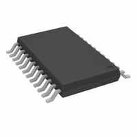
AD5204BRUZ10 Analog Devices Inc, AD5204BRUZ10 Datasheet - Page 14

AD5204BRUZ10
Manufacturer Part Number
AD5204BRUZ10
Description
IC POT DGTL QUAD 256POS 24TSSOP
Manufacturer
Analog Devices Inc
Datasheet
1.AD5204BRUZ50.pdf
(20 pages)
Specifications of AD5204BRUZ10
Taps
256
Resistance (ohms)
10K
Number Of Circuits
4
Temperature Coefficient
700 ppm/°C Typical
Memory Type
Volatile
Interface
SPI, 3-Wire Serial
Voltage - Supply
2.7 V ~ 5.5 V, ±2.3 V ~ 2.7 V
Operating Temperature
-40°C ~ 85°C
Mounting Type
Surface Mount
Package / Case
24-TSSOP
Resistance In Ohms
10K
End To End Resistance
10kohm
Track Taper
Linear
No. Of Steps
256
Resistance Tolerance
± 30%
Supply Voltage Range
2.7V To 5.5V, ± 2.3V To ± 2.7V
Control Interface
3 Wire, Serial
Lead Free Status / RoHS Status
Lead free / RoHS Compliant
Available stocks
Company
Part Number
Manufacturer
Quantity
Price
Company:
Part Number:
AD5204BRUZ10
Manufacturer:
Analog Devices Inc
Quantity:
135
Part Number:
AD5204BRUZ10
Manufacturer:
ADI/亚德诺
Quantity:
20 000
Part Number:
AD5204BRUZ10-REEL7
Manufacturer:
ADI/亚德诺
Quantity:
20 000
Company:
Part Number:
AD5204BRUZ100
Manufacturer:
ADI
Quantity:
556
Part Number:
AD5204BRUZ100
Manufacturer:
ADI/亚德诺
Quantity:
20 000
AD5204/AD5206
PROGRAMMING THE POTENTIOMETER DIVIDER
VOLTAGE OUTPUT OPERATION
The digital potentiometer easily generates an output voltage
proportional to the input voltage applied to a given terminal.
For example, connecting Terminal A to 5 V and Terminal B to
ground produces an output voltage at the wiper that can be any
value from 0 V up to 1 LSB less than +5 V. Each LSB of voltage
is equal to the voltage applied across Terminal A and Terminal B
divided by the 256-position resolution of the potentiometer
divider. The general equation defining the output voltage with
respect to ground for any given input voltage applied to
Terminal A and Terminal B is
Operation of the digital potentiometer in the divider mode
results in more accurate operation over temperature. In this
mode, the output voltage is dependent on the ratio of the
internal resistors, not the absolute value; therefore, the drift
improves to 15 ppm/°C.
V
W
(Dx) = Dx/256 × V
AB
+ V
B
Rev. C | Page 14 of 20
(3)
SHDN*
SDO*
CLK
SDI
CS
DGND
DO
DI
REG
SER
A2
A1
A0
D7
D0
8
ADDR
DEC
EN
Figure 22. Block Diagram
PR
D7
D0
D7
D0
AD5204/AD5206
LATCH
LATCH
RDAC
RDAC
4/6
R
1
R
*AD5204 ONLY
V
A1
W1
B1
A4/A6
W4/W6
B4/B6
DD


