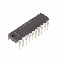
DS1802+ Maxim Integrated Products, DS1802+ Datasheet - Page 11

DS1802+
Manufacturer Part Number
DS1802+
Description
IC POT DL AUDIO TAP W/PB 20-DIP
Manufacturer
Maxim Integrated Products
Datasheet
1.DS1802.pdf
(17 pages)
Specifications of DS1802+
Taps
64
Resistance (ohms)
45K
Number Of Circuits
2
Temperature Coefficient
750 ppm/°C Typical
Memory Type
Volatile
Interface
3-Wire Serial
Voltage - Supply
2.7 V ~ 5.5 V
Operating Temperature
-40°C ~ 85°C
Mounting Type
Through Hole
Package / Case
20-DIP (0.300", 7.62mm)
Resistance In Ohms
45K
Number Of Pots
Dual
Taps Per Pot
65
Resistance
50 KOhms
Digital Interface
Serial (3-Wire)
Operating Supply Voltage
2.7 V to 5.5 V
Supply Current
2000 uA
Maximum Operating Temperature
+ 85 C
Minimum Operating Temperature
- 40 C
Description/function
Dual Audio Taper Potentiometer
Mounting Style
Through Hole
Supply Voltage (max)
5.5 V
Supply Voltage (min)
2.7 V
Tolerance
20 %
Lead Free Status / RoHS Status
Lead free / RoHS Compliant
DS1802
time window. Subsequent changes when operating with continuous input pulse occur on 100 ms time
intervals and are dependent on zero-crossing or 50 ms timeouts.
MUTE CONTROL
The DS1802 provides a mute control feature which can be accessed by the user through hardware or
software. Hardware control of the device is achieved through the MUTE input pin. This pin is internally
pulled up through a 50 k
resistor. When this input is driven low, the wiper outputs of both
potentiometers will be internally connected to the low terminal of their respective potentiometers. This
input performs as a toggle input, with the first activity on this pin connecting the wiper outputs to the low
end of the resistive array on each potentiometer. The next input activity on this pin will return the wiper
position to the previous state before the muting occurred. Also, if operating in pushbutton mode, mute
will be deactiva ted if an input is received over the VU, VD, UC0, UC1, DC0, DC1 inputs. This input, like
the pushbutton inputs, is internally debounced and requires no external circuitry. When the device
powers up, the first activity on the mute pin will internally connect the wipers to the low end of the
resistor array.
Software mute control was briefly discussed in 3-wire protocol and operation. Bits 6 and 14 of the 16-bit
I/O shift register are reserved for mute control of potentiometer-0 and potentiometer-1, respectively.
Unlike hardware mute control, software muting allows the user individual control of each potentiometer
(i.e., potentiometer-0 and potentiometer-1 can be independently muted). Software muting of
potentiometer-0 would require bit 6 to have a value of 1 while for potentiometer-1, bit 14 should have a
value 1. When the user desires to release the mute of any potentiometer through software the complete
16-bit I/O shift register must be rewritten with the desired potentiometer wiper settings and bits 6 and 14
having 0 value.
3-Wire Serial Port Vs. Pushbutton
Operation
In applications where both the 3-wire serial port and the pushbutton inputs will be used to control the
part, there may be times when activity is present on both control interfaces simultaneously. This section
describes how the DS1802 handles these situations.
In all instances, the DS1802 3-wire serial port takes precedence over pushbutton input control.
The DS1802 will not allow pushbutton inputs to change wiper position during 3-wire serial port activity.
11 of 17


