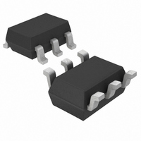
LTC2630ISC6-LZ12#TRMPBF Linear Technology, LTC2630ISC6-LZ12#TRMPBF Datasheet - Page 17

LTC2630ISC6-LZ12#TRMPBF
Manufacturer Part Number
LTC2630ISC6-LZ12#TRMPBF
Description
IC DAC 12BIT R-R SC70-6
Manufacturer
Linear Technology
Datasheet
1.LTC2630CSC6-LZ8TRMPBF.pdf
(20 pages)
Specifications of LTC2630ISC6-LZ12#TRMPBF
Settling Time
4.4µs
Number Of Bits
12
Data Interface
Serial
Number Of Converters
1
Voltage Supply Source
Single Supply
Power Dissipation (max)
480µW
Operating Temperature
-40°C ~ 85°C
Mounting Type
Surface Mount
Package / Case
SC-70-6, SC-88, SOT-363
Lead Free Status / RoHS Status
Lead free / RoHS Compliant
Other names
LTC2630ISC6-LZ12#TRMPBFTR
Available stocks
Company
Part Number
Manufacturer
Quantity
Price
OPERATION
Optoisolated 4mA to 20mA Process Controller
Figure 5 shows how to use an LTC2630HZ to make an
optoisolated, digitally-controlled 4mA to 20mA transmitter.
The transmitter circuitry, including optoisolation, is
powered by the loop voltage which has a wide range of
5.4V to 80V. The 5V output of the LT
set the 4mA offset current and V
control the 0mA to 16mA signal current. The supply
current for the regulator, DAC, and op amp is well below
the 4mA budget at zero scale. R
current, which includes the quiescent supply current and
CS/LD
SCK
SDI
X
1
X
2
CS/LD
X
SCK
SDI
3
8 DON’T-CARE BITS
X
4
X
C3
5
1
COMMAND WORD
X
C2
6
2
Figure 3a. 24-Bit Load Sequence (Minimum Input Word)
LTC2630-12 SDI Data Word: 12-Bit Input Code + 4 Don’t-Care Bits (Shown);
LTC2630-10 SDI Data Word: 10-Bit Input Code + 6 Don’t-Care Bits;
LTC2630-8 SDI Data Word: 8-Bit Input Code + 8 Don’t-Care Bits
Figure 3b. 32-Bit Load Sequence
LTC2630-12 SDI Data Word: 12-Bit Input Code + 4 Don’t-Care Bits (Shown);
LTC2630-10 SDI Data Word: 10-Bit Input Code + 6 Don’t-Care Bits;
LTC2630-8 SDI Data Word: 8-Bit Input Code + 8 Don’t-Care Bits
X
C1
7
3
X
C0
8
4
S
OUT
C3
X
9
COMMAND WORD
senses the total loop
4 DON’T-CARE BITS
5
C2
®
10
is used to digitally
X
3010-5 is used to
6
C1
X
11
7
C0
12
X
8
D11
X
13
4 DON’T-CARE BITS
32-BIT INPUT WORD
9
D10
X
14
10
X
D9
15
11
24-BIT INPUT WORD
X
D8
16
12
D11
additional current through Q1. Note that at the maximum
loop voltage of 80V, Q1 will dissipate 1.6W when I
20mA and must have an appropriate heat sink.
R
for controlling a 4mA to 20mA output as the digital input
varies from zero scale to full scale. Alternatively, R
can be a 365k, 1% resistor in series with a 20k trim pot
and R
trim pot. The optoisolators shown will limit the speed of
the serial bus; the 6N139 is an alternative that will allow
higher data rates.
D7
17
13
OFFSET
D10
D6
18
14
GAIN
D9
D5
19
15
and R
D8
DATA WORD
D4
can be a 75.0k, 1% resistor in series with a 5k
20
16
D7
D3
21
GAIN
17
D6
D2
22
18
are the closest 0.1% values to ideal
D5
D1
23
19
DATA WORD
D4
D0
24
20
D3
X
25
21
D2
26
X
22
D1
27
X
23
D0
28
X
24
LTC2630
X
29
2630 F03a
X
30
X
31
17
OFFSET
X
32
OUT
2630fe
2630 F03b
=


