08053E104ZAT2A AVX Corporation, 08053E104ZAT2A Datasheet - Page 45
08053E104ZAT2A
Manufacturer Part Number
08053E104ZAT2A
Description
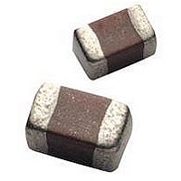
CAPACITOR CERAMIC, 0.1UF, 25V, Z5U, 0805
Manufacturer
AVX Corporation
Datasheet
1.12065E104MAT2A.pdf
(49 pages)
Specifications of 08053E104ZAT2A
Dielectric Characteristic
Z5U
Capacitance
0.1µF
Capacitance Tolerance
+80, -20%
Voltage Rating
25VDC
Capacitor Case Style
0805
No. Of Pins
2
Capacitor Mounting
SMD
Rohs Compliant
Yes


44
Surface Mounting Guide
MLC Chip Capacitors
Component Pad Design
Component pads should be designed to achieve good sol-
der filets and minimize component movement during reflow
soldering. Pad designs are given below for the most com-
mon sizes of multilayer ceramic capacitors for both wave
and reflow soldering. The basis of these designs is:
• Pad width equal to component width. It is permissible to
• Pad overlap 0.5mm beneath component.
• Pad extension 0.5mm beyond components for reflow and
REFLOW SOLDERING
Dimensions in millimeters (inches)
decrease this to as low as 85% of component width but it
is not advisable to go below this.
1.0mm for wave soldering.
D1
D2
D3
D4
D5
Case Size
0402
0603
0805
1206
1210
1808
1812
1825
2220
2225
1.70 (0.07)
2.30 (0.09)
3.00 (0.12)
4.00 (0.16)
4.00 (0.16)
5.60 (0.22)
5.60 (0.22)
5.60 (0.22)
6.60 (0.26)
6.60 (0.26)
D1
1.00 (0.04))
0.60 (0.02)
0.80 (0.03)
1.00 (0.04)
1.00 (0.04)
1.00 (0.04)
1.00 (0.04)
1.00 (0.04)
1.00 (0.04)
1.00 (0.04)
D2
0.50 (0.02)
0.70 (0.03)
1.00 (0.04)
2.00 (0.09)
2.00 (0.09)
3.60 (0.14)
3.60 (0.14)
3.60 (0.14)
4.60 (0.18)
4.60 (0.18)
D3
0.60 (0.02)
0.80 (0.03)
1.00 (0.04)
1.00 (0.04)
1.00 (0.04)
1.00 (0.04)
1.00 (0.04)
1.00 (0.04)
1.00 (0.04)
1.00 (0.04)
D4
0.50 (0.02)
0.75 (0.03)
1.25 (0.05)
1.60 (0.06)
2.50 (0.10)
2.00 (0.08)
3.00 (0.12)
6.35 (0.25)
5.00 (0.20)
6.35 (0.25)
D5
Related parts for 08053E104ZAT2A
Image
Part Number
Description
Manufacturer
Datasheet
Request
R

Part Number:
Description:
Manufacturer:
AVX Corporation
Datasheet:
Part Number:
Description:
Manufacturer:
AVX Corporation
Datasheet:
Part Number:
Description:
Manufacturer:
AVX Corporation
Datasheet:
Part Number:
Description:
Manufacturer:
AVX Corporation
Datasheet:
Part Number:
Description:
Manufacturer:
AVX Corporation
Datasheet: