LTC2704CGW-14#TRPBF Linear Technology, LTC2704CGW-14#TRPBF Datasheet - Page 5
LTC2704CGW-14#TRPBF
Manufacturer Part Number
LTC2704CGW-14#TRPBF
Description
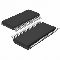
IC DAC 14BIT QUAD VOUT 44-SSOP
Manufacturer
Linear Technology
Datasheet
1.LTC2704IGW-12PBF.pdf
(22 pages)
Specifications of LTC2704CGW-14#TRPBF
Settling Time
9µs
Number Of Bits
14
Data Interface
Serial, SPI™
Number Of Converters
4
Voltage Supply Source
Analog and Digital, Dual ±
Operating Temperature
0°C ~ 70°C
Mounting Type
Surface Mount
Package / Case
44-SSOP
Lead Free Status / RoHS Status
Lead free / RoHS Compliant
Power Dissipation (max)
-
Available stocks
Company
Part Number
Manufacturer
Quantity
Price


temperature range, otherwise specifi cations are T
REFG1 = REFG2 = GND = 0V.
ELECTRICAL CHARACTERISTICS
SYMBOL
C
TIMING CHARACTERISTICS
SYMBOL
V
t
t
t
t
t
t
t
t
t
t
t
t
t
V
t
t
t
t
t
t
t
t
t
t
t
t
t
Note 1: Stresses beyond those listed under Absolute Maximum Ratings
may cause permanent damage to the device. Exposure to any Absolute
Maximum Rating condition for extended periods may affect device
reliability and lifetime.
Note 2: The notation V
voltage is applied to both pins.
Note 3: Guaranteed by design, not subject to test.
range, otherwise specifi cations are at T
1
2
3
4
5
6
7
8
9
10
11
12
13
1
2
3
4
5
6
7
8
9
10
11
12
13
IN
DD
DD
= 4.5V to 5.5V
= 2.7V to 3.3V
PARAMETER
SDI Valid to SCK Setup
SDI Valid to SCK Hold
SCK High Time
SCK Low Time
CS/LD Pulse Width
LSB SCK High to CS/LD High
CS/LD Low to SCK Positive Edge
CS/LD High to SCK Positive Edge
SRO Propagation Delay
CLR Pulse Width
LDAC Pulse Width
CLR Low to RFLAG Low
CS/LD High to RFLAG High
SCK Frequency
SDI Valid to SCK Setup
SDI Valid to SCK Hold
SCK High Time
SCK Low Time
CS/LD Pulse Width
LSB SCK High to CS/LD High
CS/LD Low to SCK Positive Edge
CS/LD High to SCK Positive Edge
SRO Propagation Delay
CLR Pulse Width
LDAC Pulse Width
CLR Low to RFLAG Low
CS/LD High to RFLAG High
SCK Frequency
PARAMETER
Digital Input Capacitance
+
is used to denote both V
A
= 25°C.
+
1
and V
+
A
2
= 25°C, V
CONDITIONS
V
CONDITIONS
C
C
C
50% Duty Cycle (Note 5)
C
C
C
50% Duty Cycle (Note 5)
when the same
The
LOAD
LOAD
LOAD
LOAD
LOAD
LOAD
IN
= 0V (Note 3)
l
= 10pF
= 10pF (Note 3)
= 10pF (Note 3)
= 10pF
= 10pF
= 10pF
The
denotes specifi cations which apply over the full operating temperature
+
1
l
= V
denotes specifi cations which apply over the full operating
+
2
= 15V, V
Note 4: Measured in unipolar 0V to 5V mode.
Note 5: When using SRO, maximum SCK frequency f
propagation delay as follows:
f
MAX
–
=
= –15V, V
2 t
(
9
1
+ t
S
DD
)
= 5V, REF1 = REF2 = 5V, AGND = AGNDx =
, where t
l
l
l
l
l
l
l
l
l
l
l
l
l
l
l
l
l
l
l
l
l
l
l
l
l
l
l
l
l
s
is the setup time of the receiving device.
MIN
MIN
11
11
12
12
50
15
15
15
12
12
12
90
20
7
7
9
0
9
9
0
TYP
TYP
LTC2704
MAX
MAX
MAX
is limited by SRO
18
50
40
40
26
70
60
25
5
UNITS
UNITS
2704fc
5
MHz
MHz
pF
ns
ns
ns
ns
ns
ns
ns
ns
ns
ns
ns
ns
ns
ns
ns
ns
ns
ns
ns
ns
ns
ns
ns
ns
ns
ns
Related parts for LTC2704CGW-14#TRPBF
Image
Part Number
Description
Manufacturer
Datasheet
Request
R

Part Number:
Description:
IC,D/A CONVERTER,QUAD,16-BIT,CMOS,SOP,44PIN
Manufacturer:
Linear Technology
Datasheet:

Part Number:
Description:
IC DAC 12BIT QUAD VOUT 44-SSOP
Manufacturer:
Linear Technology
Datasheet:
Part Number:
Description:
IC DAC 12BIT QUAD VOUT 44-SSOP
Manufacturer:
Linear Technology
Datasheet:
Part Number:
Description:
IC DAC 16BIT QUAD VOUT 44-SSOP
Manufacturer:
Linear Technology
Datasheet:
Part Number:
Description:
IC DAC 14BIT QUAD VOUT 44-SSOP
Manufacturer:
Linear Technology
Datasheet:
Part Number:
Description:
IC DAC 16BIT QUAD VOUT 44-SSOP
Manufacturer:
Linear Technology
Datasheet:
Part Number:
Description:
IC,D/A CONVERTER,QUAD,12-BIT,CMOS,SOP,44PIN
Manufacturer:
Linear Technology
Part Number:
Description:
IC,D/A CONVERTER,QUAD,12-BIT,CMOS,SOP,44PIN
Manufacturer:
Linear Technology
Part Number:
Description:
IC,D/A CONVERTER,QUAD,14-BIT,CMOS,SOP,44PIN
Manufacturer:
Linear Technology
Part Number:
Description:
IC,D/A CONVERTER,QUAD,14-BIT,CMOS,SOP,44PIN
Manufacturer:
Linear Technology
Part Number:
Description:
IC,D/A CONVERTER,QUAD,16-BIT,CMOS,SOP,44PIN
Manufacturer:
Linear Technology

Part Number:
Description:
Quad 12-, 14- and 16-Bit Voltage Output SoftSpan DACs with Readback
Manufacturer:
LINER [Linear Technology]
Datasheet:
Part Number:
Description:
CD ROM LINEARVIEW DATASHEETS
Manufacturer:
Linear Technology

Part Number:
Description:
Standalone Linear Li-Ion Battery Charger with Thermal Regulation in ThinSOT
Manufacturer:
Linear Technology Corporation
Datasheet:
Part Number:
Description:
Low noise, high frequency, 8th order linear phase lowpass filter
Manufacturer:
Linear Technology Corporation
Datasheet: