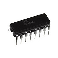
7802801EA MICROSEMI, 7802801EA Datasheet - Page 5

7802801EA
Manufacturer Part Number
7802801EA
Description
Manufacturer
MICROSEMI
Datasheet
1.7802801EA.pdf
(6 pages)
Specifications of 7802801EA
Number Of Pwm Outputs
2
On/off Pin
Yes
Adjustable Output
No
Topology
Push-Pull
Switching Freq
300KHz
Operating Supply Voltage (max)
40V
Synchronous Pin
No
Operating Temperature Classification
Military
Mounting
Through Hole
Pin Count
16
Package Type
CDIP
Lead Free Status / Rohs Status
Supplier Unconfirmed
Available stocks
Company
Part Number
Manufacturer
Quantity
Price
Rev 1.1a
Copyright
APPLICATION NOTES (continued)
CURRENT LIMITING
The current limiting circuitry of the SG1524 is shown in Figure 3.
By matching the base-emitter voltages of Q1 and Q2, and
assuming a negligible voltage drop across R1:
Although this circuit provides a relatively small threshold with a
negligible temperature coefficient, there are some limitations to
its use because of its simplicity.
The most important of these is the limited common-mode voltage
range: ±0.3 volts around ground. This requires sensing in the
ground or return line of the power supply. Also precautions
should be taken to not turn on the parasitic substrate diode of the
integrated circuit, even under transient conditions. A Schottky
clamp diode at Pin 5 may be required in some configurations to
achieve this.
In this conventional single-ended regulator circuit, the two out-
puts of the SG1524 are connected in parallel for effective 0 - 90%
duty-cycle modulation. The use of an output inductor requires
and R-C phase compensation network for loop stability.
C.L. Threshold = V
1994
~ 200 mV
BE
(Q1) + I
1
• R
2
- V
BE
(Q2) = I
FIGURE 3 - CURRENT LIMITING CIRCUITRY OF THE SG1524
1
• R
2
5
A second factor to consider is that the response time is relatively
slow. The current limit amplifier is internally compensated by R
, C
pins. A constant current of approximately 150 A flows out of Pin
4, and a variable current with a range of 0-150 A flows out of Pin
5. As a result, the equivalent source impedance seen by the
current sense pins should be less than 50 ohms to keep the
threshold error less than 5%.
Since the gain of this circuit is relatively low (42 dB), there is a
transition region as the current limit amplifier takes over pulse
width control from the error amplifier. For testing purposes,
threshold is defined as the input voltage required to get 25% duty
cycle (+2 volts at the error amplifier output) with the error amplifier
signaling maximum duty cycle.
APPLICATION NOTE: If the current limit function is not used on
the SG1524, the common-mode voltage range restriction re-
quires both current sense pins to be grounded.
Push-pull outputs are used in this transformer-coupled DC-DC
regulating converter. Note that the oscillator must be set at twice
the desired output frequency as the SG1524's internal flip-flop
divides the frequency by 2 as it switches the P.W.M. signal from
one output to the other. Current limiting is done here in the
primary so that the pulse width will be reduced should transformer
saturation occur.
A third factor to consider is the bias current of the C.L. Sense
1 ,
and Q1, resulting in a roll-off pole at approximately 300 Hz.
11861 Western Avenue
(714) 898-8121
Garden Grove, CA 92841
FAX: (714) 893-2570
1


