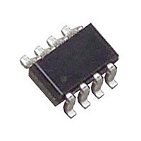
LTC2954ITS8-2#PBF Linear Technology, LTC2954ITS8-2#PBF Datasheet - Page 13

LTC2954ITS8-2#PBF
Manufacturer Part Number
LTC2954ITS8-2#PBF
Description
Manufacturer
Linear Technology
Datasheet
1.LTC2954ITS8-2PBF.pdf
(16 pages)
Specifications of LTC2954ITS8-2#PBF
Operating Temperature (min)
-40C
Operating Temperature Classification
Industrial
Operating Temperature (max)
85C
Rad Hardened
No
Lead Free Status / Rohs Status
Compliant
Available stocks
Company
Part Number
Manufacturer
Quantity
Price
TYPICAL APPLICATIO S
capacitor extends the length of time (beyond 64ms) that
the ⎯ P ⎯ B input must be held low before releasing the enable
output.
High Voltage Power Path Switching
The high voltage ⎯ E ⎯ N open drain output of the LTC2954-2
is designed to switch on/off an external power PFET. This
allows a user to connect/disconnect a power supply (or
battery) to its load by toggling the ⎯ P ⎯ B pin. Figure 7 shows
the LTC2954-2 controlling a two cell Li-Ion battery ap-
plication. The ⎯ K ⎯ I ⎯ L ⎯ L pin is connected to the output of the
PFET through a resistive divider. The ⎯ K ⎯ I ⎯ L ⎯ L pin serves as
a voltage monitor. When V
Li-Ion BATTERY
Li-Ion BATTERY
SINGLE CELL
SINGLE CELL
OUT
4.2V
4.2V
drops below 6V, causing a
+
+
PARASITICS
CERAMIC
Figure 7. Power Path Control with 6V Under Voltage Detect
U
0.1µF
C4
NOISE
INDUCTANCE
CAPACITANCE
TRACE
TRACE
V
PB
GND ONT
IN
Figure 8. Noisy ⎯ P ⎯ B Trace
LTC2954-2
C
0.033µF
R5
100K
ONT
5.1k
0.1µF
R6
C5
*
KILL
PDT
INT
EN
V
⎯ K ⎯ I ⎯ L ⎯ L voltage below V
circuit 30µs later. Since the PDT pin is open circuited, the
power down debounce time defaults to 64ms.
⎯ P ⎯ B Pin in a Noisy Environment
The rugged ⎯ P ⎯ B pin is designed to operate in noisy envi-
ronments. Transients below ground (>–6V) and above V
(<33V) will not damage the rugged ⎯ P ⎯ B pin. Additionally,
the ⎯ P ⎯ B pin can withstand ESD HBM strikes up to ±10kV.
In order to keep external noise from coupling inside the
LTC2954, place an R-C network close to the ⎯ P ⎯ B pin. A
5.1k resistor and a 0.1µF capacitor should suffi ce for most
noisy applications (see Figure 8).
IN
V
TH
= 0.6V INPUT
R9
100K
GND
V
PB
IN
M1
*OPTIONAL
DETAILS OMITTED
FOR CLARITY
LTC2954-1
ONT
100k
1%
R4
KILL
PDT
INT
EN
⎯ K ⎯ I ⎯ L ⎯ L (TH)
OPTIONAL GLITCH
FILTER CAPACITOR
R1
909k
1%
2954 F08
V
OUT
V
OUT
,TRIP POINT = 6V
, the ⎯ E ⎯ N pin becomes an open
C3*
0.1µF
2954 F07
LTC2954
13
2954fa
IN


