99A2A-C28-A13/R50 Bourns Inc., 99A2A-C28-A13/R50 Datasheet - Page 3
99A2A-C28-A13/R50
Manufacturer Part Number
99A2A-C28-A13/R50
Description
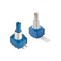
Panel Mount Potentiometers 5/8 5K 10% SINGLE TURN
Manufacturer
Bourns Inc.
Datasheet
1.99A2A-C28-A13R50L.pdf
(6 pages)
Specifications of 99A2A-C28-A13/R50
Resistance
5 KOhms
Tolerance
10 %
Power Rating
2 Watts
Termination Style
Lug
Taper
Linear
Number Of Turns
1
Element Type
Cermet
Shaft Type
Flatted / D
Shaft Length
7/8 in
Shaft Diameter
1/4 in
Operating Temperature Range
- 40 C to + 125 C
Product
Panel Mount Potentiometers
Lead Free Status / Rohs Status
Lead free / RoHS Compliant


Customers should verify actual device performance in their specifi c applications.
Contacts:
Power Rating (Resistive Load):
Contact Resistance (0.1 VDC-10 mA) ...............................................................................................................................10 milliohms nominal
Contact Bounce ...........................................................................................................................................................5 milliseconds maximum
Dielectric Withstanding Voltage (MIL-STD-202, Method 301)
Insulation Resistance ................................................................................................................................................. 1000 megohms minimum
Operating Temperature Range .................................................................................................................................................... 0 °C to +70 °C
Exposure Temperature Range ................................................................................................................................................-65 °C to +125 °C
Vibration (Dual Section).................................................................................................................................................................................. 8 G
Shock (Dual Section).................................................................................................................................................................................... 20 G
Rotational Life ................................................................................................................................................................................25,000 cycles
Moisture Resistance (MIL-STD-202, Method 106, Condition B)
Housing Material .......................................................................................................High temperature, fl ame retardant, thermosetting plastic
Actuating Torque (Each Section, Switch Module Only) .............................................................................. 3.53 to 10.59 N-cm (5 to 15 oz.-in.)
Running Torque (Out of Detent, 2-4 Module Assembly) ............................................................................. 0.21 to 1.41 N-cm (0.3 to 2 oz.-in.)
Detent ................................................................................................................................................................................CW or CCW standard
Actuation Angle ......................................................................................................................................................................................20 ° ±5 °
Contact Materials .................................................................................................................................................... Fine silver with gold overlay
Terminal Styles .............................................................................................................................................................................Solder lug only
Terminal Strength (Before and After Soldering Heat Exposure) .................................................................................... 0.9 kg (2 lbs.) minimum
NOTE:
1
Specifi cations are subject to change without notice.
At room ambient: +25 °C nominal and 50 % relative humidity nominal, except as noted.
Rotary Switch Specifi cations
Initial Electrical Characteristics
Environmental Characteristics
Mechanical Characteristics
DPST ........................................................................................................................................................N.O/N.O., N.C./N.C. or N.O./N.C.
DPDT ..........................................................................................................................................................2 N.O./N.C. (break before make)
DPST ..................................................................................... 2 A @ 125 volts RMS-60 Hz or 2 A @ 28 VDC, 1 A @ 250 volts RMS-60 Hz
DPDT .....................................................................................................................................1 A @ 125 volts RMS-60 Hz or 1 A @ 28 VDC
Sea Level ........................................................................................................................................................................1500 VAC minimum
Contact Resistance .................................................................................................................................................. 10 milliohms maximum
Contact Bounce ................................................................................................................................................... 0.1 millisecond maximum
Switch Actuating Torque (50% Duty cycle @ Rated Power Load) ........................................................... 1.41 to 4.94 N-cm (2 to 7 oz.-in.)
Contact Resistance ................................................................................................................................................ 100 milliohms maximum
Contact Resistance (0.1 VDC-10 mA) ..................................................................................................................... 10 milliohms maximum
Insulation Resistance (After 24 Hours @ Room Temperature) (500 VDC) ..............................................................100 megohms minimum
Standard Orientation ........................................................................................................................................ In-line with control terminals
Optional ....................................................................................................................................................Rotated 90 ° CCW from standard
Model 97 & 99
Performance specifi cations do not apply to units subjected to printed circuit board cleaning procedures.
- 5/8 ” Square Single-Turn Panel Control with Rotary Switch
1
1
1
Related parts for 99A2A-C28-A13/R50
Image
Part Number
Description
Manufacturer
Datasheet
Request
R

Part Number:
Description:
Panel Mount Potentiometers 5/8 5K 10% SINGLE TURN
Manufacturer:
Bourns Inc.
Datasheet:

Part Number:
Description:
Manufacturer:
Bourns, Inc.
Datasheet:
Part Number:
Description:
11mm Potentiometer
Manufacturer:
Bourns, Inc.
Datasheet:
Part Number:
Description:
Manufacturer:
Bourns, Inc.
Datasheet:
Part Number:
Description:
Manufacturer:
Bourns, Inc.
Datasheet:
Part Number:
Description:
Manufacturer:
Bourns, Inc.
Datasheet:
Part Number:
Description:
5/16 Round Trimming Potentiometer
Manufacturer:
Bourns, Inc.
Datasheet:
Part Number:
Description:
4100R Series: Thick Film Moulded DIPs - Resistor Networks
Manufacturer:
Bourns, Inc.
Datasheet:
Part Number:
Description:
PROTECTOR - SINGLE BIDIRECTIONAL
Manufacturer:
Bourns, Inc.