ADSP-21371KSWZ-2B Analog Devices Inc, ADSP-21371KSWZ-2B Datasheet - Page 5
ADSP-21371KSWZ-2B
Manufacturer Part Number
ADSP-21371KSWZ-2B
Description
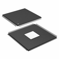
IC DSP 32BIT 266MHZ 208-LQFP
Manufacturer
Analog Devices Inc
Series
SHARC®r
Type
Floating Pointr
Specifications of ADSP-21371KSWZ-2B
Package / Case
208-LQFP
Interface
DAI, DPI
Operating Temperature
0°C ~ 70°C
Clock Rate
266MHz
Non-volatile Memory
ROM (512 kB)
On-chip Ram
128kB
Voltage - I/o
3.30V
Voltage - Core
1.20V
Mounting Type
Surface Mount
Svhc
No SVHC (18-Jun-2010)
Base Number
21371
Core Frequency Typ
266MHz
Dsp Type
Floating Point
Mmac
532
No. Of Pins
208
Interface Type
SPI, UART
Rohs Compliant
Yes
Operating Temperature Range
0°C To +70°C
Lead Free Status / RoHS Status
Lead free / RoHS Compliant
Available stocks
Company
Part Number
Manufacturer
Quantity
Price
Company:

Part Number:
ADSP-21371KSWZ-2B
Manufacturer:
Analog Devices Inc
Quantity:
10 000
Part Number:
ADSP-21371KSWZ-2B
Manufacturer:
ADI/亚德诺
Quantity:
20 000


ments. These computation units support IEEE 32-bit single-
precision floating-point, 40-bit extended precision floating-
point, and 32-bit fixed-point data formats.
Data Register File
A general-purpose data register file is contained in each pro
cessing element. The register files transfer data between the
computation units and the data buses, and store intermediate
results. These 10-port, 32-register (16 primary, 16 secondary)
register files, combined with the ADSP-2136x enhanced Har
vard architecture, allow unconstrained data flow between
computation units and internal memory. The registers in PEX
are referred to as R0-R15 and in PEY as S0-S15.
Single-Cycle Fetch of Instruction and Four Operands
The ADSP-21371 features an enhanced Harvard architecture in
which the data memory (DM) bus transfers data and the pro
gram memory (PM) bus transfers both instructions and data
(see
gram and data memory buses and on-chip instruction cache,
the processor can simultaneously fetch four operands (two over
each data bus) and one instruction (from the cache), all in a sin
gle cycle.
Instruction Cache
The ADSP-21371 includes an on-chip instruction cache that
enables three-bus operation for fetching an instruction and four
data values. The cache is selective—only the instructions whose
fetches conflict with PM bus data accesses are cached. This
cache allows full speed execution of core, looped operations
such as digital filter multiply-accumulates, and FFT butterfly
processing.
Data Address Generators With Zero-Overhead Hardware
Circular Buffer Support
The ADSP-21371’s two data address generators (DAGs) are
used for indirect addressing and implementing circular data
buffers in hardware. Circular buffers allow efficient program
ming of delay lines and other data structures required in digital
signal processing, and are commonly used in digital filters and
Fourier transforms. The two DAGs of the ADSP-21371 contain
sufficient registers to allow the creation of up to 32 circular buff
ers (16 primary register sets, 16 secondary). The DAGs
automatically handle address pointer wraparound, reduce over
head, increase performance, and simplify implementation.
Circular buffers can start and end at any memory location.
Flexible Instruction Set
The 48-bit instruction word accommodates a variety of parallel
operations, for concise programming. For example, the
ADSP-21371 can conditionally execute a multiply, an add, and a
subtract in both processing elements while branching and fetch
ing up to four 32-bit values from memory—all in a single
instruction.
Figure 1 on page
1). With the ADSP-21371’s separate pro
Rev. 0 | Page 5 of 48 | June 2007
ADSP-21371 MEMORY
The ADSP-21371 adds the following architectural features to
the SIMD SHARC family core.
On-Chip Memory
The ADSP-21371 contains 1 megabit of internal RAM and four
megabits of internal mask-programmable ROM. Each block can
be configured for different combinations of code and data stor
age (see
single-cycle, independent accesses by the core processor and I/O
processor. The ADSP-21371 memory architecture, in combina
tion with its separate on-chip buses, allow two data transfers
from the core and one from the I/O processor, in a single cycle.
The ADSP-21371’s SRAM can be configured as a maximum of
32k words of 32-bit data, 64k words of 16-bit data, 21.3k words
of 48-bit instructions (or 40-bit data), or combinations of differ
ent word sizes up to 1 megabit. All of the memory can be
accessed as 16-bit, 32-bit, 48-bit, or 64-bit words. A 16-bit float
ing-point storage format is supported that effectively doubles
the amount of data that may be stored on-chip. Conversion
between the 32-bit floating-point and 16-bit floating-point for
mats is performed in a single instruction. While each memory
block can store combinations of code and data, accesses are
most efficient when one block stores data using the DM bus for
transfers, and the other block stores instructions and data using
the PM bus for transfers.
Using the DM bus and PM buses, with one bus dedicated to a
memory block, assures single-cycle execution with two data
transfers. In this case, the instruction must be available in the
cache.
EXTERNAL MEMORY
The external port on the ADSP-21371 SHARC provides a high
performance, glueless interface to a wide variety of industry-
standard memory devices. The 32-bit wide bus may be used to
interface to synchronous and/or asynchronous memory devices
through the use of its separate internal memory controllers: the
first is an SDRAM controller for connection of industry-stan
dard synchronous DRAM devices and DIMMs (dual inline
memory module), while the second is an asynchronous memory
controller intended to interface to a variety of memory devices.
Four memory select pins enable up to four separate devices to
coexist, supporting any desired combination of synchronous
and asynchronous device types. Non SDRAM external memory
address space is shown in
External Memory Execution
In the ADSP-21371, the program sequencer can execute code
directly from external memory bank 0 (SRAM, SDRAM). This
allows a reduction in internal memory size, thereby reducing
the die area. With external execution, programs run at slower
speeds since 48-bit instructions are fetched in parts from a 32
bit external bus coupled with the inherent latency of fetching
instructions from SDRAM. Fetching instructions from external
memory generally takes 1.5 peripheral clock cycles per
instruction.
Table 2 on Page
6). Each memory block supports
Table
3.
ADSP-21371
Related parts for ADSP-21371KSWZ-2B
Image
Part Number
Description
Manufacturer
Datasheet
Request
R

Part Number:
Description:
±1.7g Dual-Axis IMEMS Accelerometer Evaluation Board
Manufacturer:
Analog Devices Inc
Datasheet:

Part Number:
Description:
Inertial Sensor Evaluation System
Manufacturer:
Analog Devices Inc
Datasheet:
Part Number:
Description:
Manufacturer:
Analog Devices Inc
Datasheet:
Part Number:
Description:
Manufacturer:
Analog Devices Inc
Datasheet:
Part Number:
Description:
Manufacturer:
Analog Devices Inc
Datasheet:
Part Number:
Description:
Manufacturer:
Analog Devices Inc
Datasheet:
Part Number:
Description:
Manufacturer:
Analog Devices Inc
Datasheet:
Part Number:
Description:
Manufacturer:
Analog Devices Inc
Datasheet:
Part Number:
Description:
Manufacturer:
Analog Devices Inc
Datasheet:
Part Number:
Description:
Manufacturer:
Analog Devices Inc
Datasheet:
Part Number:
Description:
Manufacturer:
Analog Devices Inc
Datasheet:
Part Number:
Description:
Manufacturer:
Analog Devices Inc
Datasheet:
Part Number:
Description:
Manufacturer:
Analog Devices Inc
Datasheet: