142-4308-401 Emerson Network Power, 142-4308-401 Datasheet - Page 116
142-4308-401
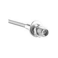
Manufacturer Part Number
142-4308-401
Description
RF Connectors BLHD JCK 142/400 GLD
Manufacturer
Emerson Network Power
Datasheet
1.133-3711-801.pdf
(294 pages)
Specifications of 142-4308-401
Product
Connector
Rf Series
SMA
Gender
Receptacle
Polarity
Reverse
Contact Plating
Gold
Shell Plating
Gold
Impedance
50 Ohms
Termination Style
Crimp, Solder
Body Style
Straight
Connector Type
Jack
Maximum Frequency
12.4 GHz
Lead Free Status / Rohs Status
Lead free / RoHS Compliant


116
SMC - 50 Ohm Connectors
Specifications
INCHES (MILLIMETERS) • CUSTOMER DRAWINGS AVAILABLE ON REQUEST
** All gold plated parts include a .00005" min. nickel underplate barrier layer.
†
ELECTRICAL RATINGS
Impedance: 50 Ohms
Frequency Range: 0-10 GHz
VSWR: (f = GHz)
RG-178 cable ................................... 1.25 + .04f
RG-316 and .086 Semi-Rigid
Uncabled receptacles ............................ N/A
Adapters ........................................... 1.20 + .04f
Working Voltage: (VRMS maximum)
Connectors for Cable Type
Dielectric Withstanding Voltage: (VRMS minimum at sea level)
Corona Level: (Volts minimum at 70,000 feet)
Insertion Loss: (dB maximum, tested at 4 GHz)
Insulation Resistance: 1000 megohms minimum
Contact Resistance: (milliohms maximum)
Center contact (straight cabled
Center contact (right angle cabled
Outer contact (gold plated connectors) ................. 1.0
Outer contact (nickel plated connectors) ............... 2.5
Braid to body (gold plated connectors) ................. 1.0
Braid to body (nickel plated connectors) ............... 2.5
RF Leakage: (dB minimum tested at 2.5 GHz)
Avoid user injury due to misapplication. See safety advisory definitions inside front cover.
cable ............................................. 1.20 + .04f
RG-178 ............................................... 250
RG-316, .086 Semi-Rigid
Connectors for RG-178 ........................................................................... 750
Connectors for RG-316, .086 Semi-Rigid
Connectors for RG-178 ........................................................................... 185
Connectors for RG-316, .086 Semi-Rigid ................................................ 250
Uncabled receptacles and adapters ........................................................ N/A
Straight cable connectors .................................................................. 0.25 dB
Right angle cable connectors ............................................................ 0.50 dB
Uncabled receptacles and adapters ........................................................ N/A
connectors and uncabled receptacles) .............. 6.0
Cable connectors ............................................................................... -55 dB
Uncabled receptacles and adapters ........................................................ N/A
connectors and adapters) ................................ 12.0
uncabled receptacles, adapters ........ 335
uncabled receptacles, adapters ........................................................... 1000
Connectivity Solutions
PLUG
Straight Cabled
†
Sea Level
Tel: 800-247-8256
†
Initial
Mating Engagement for SMC Series
Right Angle Cabled
1.40 + .06f
1.30 + .04f
70K Feet
60
85
Environmental
•
†
Fax: 507-833-6287
After
16.0
N/A
N/A
N/A
N/A
8.0
JACK
RF High Potential Withstanding Voltage: (VRMS minimum, tested at
MECHANICAL RATINGS
Engagement Design: MIL-PRF-39012, Series SMC
Engagement/Disengagement Force: 16 inch-ounce maximum torque
Mating Torque: 35 to 50 inch-ounce
Coupling Proof Torque: 100 inch-ounce minimum
Coupling Nut Retention: 35 pounds minimum
Contact Retention: 4 lbs. minimum axial force (captivated contacts)
Cable Retention:
Connectors for RG-178 ................................. 10
Connectors for RG-316 ................................. 20
Connectors for .086 Semi-Rigid .................... 30
* or cable breaking strength whichever is less
Durability: 500 cycles minimum
ENVIRONMENTAL RATINGS
(Meets or exceeds the applicable paragraph of MIL-C-39012
Temperature Range: - 65
Thermal Shock: MIL-STD-202, Method 107, Condition B
Corrosion: MIL-STD-202, Method 101, Condition B
Shock: MIL-STD-210, Method 213, Condition C
Vibration: MIL-STD-202, Method 204, Condition D
MATERIAL SPECIFICATIONS
Bodies: Brass per QQ-B-626, gold plated** per MIL-G-45204 .00001"
Contacts: Male - brass per QQ-B-626, gold plated per MIL-G-45204
Nut Retention Spring: Beryllium copper per QQ-C-533, unplated
Insulators: PTFE fluorocarbon per ASTM D 1710 and ASTM D 1457
Expansion Caps: Brass per QQ-B-613, gold plated per MIL-G-45204
Crimp Sleeves: Copper per WW-T-799, gold plated per MIL-G-45204
Mounting Hardware: Brass (nuts) per QQ-B-626 or phosphor bronze
4 and 7 MHz)
Connectors for RG-178 ................................................................ 500
Connectors for RG-316 ................................................................ 700
Uncabled receptacles and adapters ............................................. 600
.00003" min.
Female - beryllium copper per QQ-C-530, gold plated per MIL-G-45204
min or nickel plated per QQ-N-290
.00003" min.
.00001" min. or nickel plated per QQ-N-290
.00001" min. or nickel plated per QQ-N-290
(lockwashers) per QQ-B-750, gold plated per MIL-G-45204 .00001"
min. or nickel plated per QQ-N-290
•
www.EmersonNetworkPower.com/connectivity
†
1 inch-ounce minimum torque (uncabled receptacles)
°
C to + 165
NOTES
1. Inside of contact to meet VSWR,
PLUG
Axial Force* (lbs)
mating characteristics and connec-
tor durability when mated with a dia
.019/.021 (0.48/0.53) male contact.
°
C
Torque (in-oz)
JACK
N/A
N/A
16
Related parts for 142-4308-401
Image
Part Number
Description
Manufacturer
Datasheet
Request
R

Part Number:
Description:
RF Connectors BLHD JCK 142/400 Ni
Manufacturer:
Emerson Network Power
Datasheet:

Part Number:
Description:
CONN JACK BULKHEAD PCB .281" GOL
Manufacturer:
Emerson Network Power
Datasheet:

Part Number:
Description:
KIT RF ADAPTER 50 OHM 70PCS
Manufacturer:
Emerson Network Power
Datasheet:

Part Number:
Description:
CONN RECEPT STRAIGHT PCB .155" G
Manufacturer:
Emerson Network Power
Datasheet:

Part Number:
Description:
CONN PLUG SMA .086S-RIG SLD NCKL
Manufacturer:
Emerson Network Power
Part Number:
Description:
CONN JACK BULKHEAD END LAUNCH SM
Manufacturer:
Emerson Network Power
Datasheet:
Part Number:
Description:
CONN JACK RECEPT RA PCB .200" GO
Manufacturer:
Emerson Network Power
Datasheet:

Part Number:
Description:
CONN JACK BULKHEAD SMA R/A GOLD
Manufacturer:
Emerson Network Power
Datasheet:
Part Number:
Description:
CONN JACK BULKHEAD SMA R/A NICKL
Manufacturer:
Emerson Network Power
Datasheet:
Part Number:
Description:
CONN JACK RA BULKHEAD GOLD SMA
Manufacturer:
Emerson Network Power
Datasheet:
Part Number:
Description:
AC/DC Front end 12Vo 36A 12Vsb Standard Airflow
Manufacturer:
Emerson Network Power

Part Number:
Description:
POWER SUPPLY DIN 24VDC 10A
Manufacturer:
Emerson Network Power
Datasheet:

Part Number:
Description:
POWER SUPPLY SGL 48VOUT 40W 3X5"
Manufacturer:
Emerson Network Power
Datasheet:

Part Number:
Description:
POWER SUP MED&ITE 48V 45W 2"X4"
Manufacturer:
Emerson Network Power
Datasheet:

Part Number:
Description:
POWER SUPPLY 60W 12V OUT
Manufacturer:
Emerson Network Power
Datasheet: