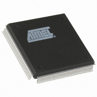
AT40K10-2CQC Atmel, AT40K10-2CQC Datasheet - Page 16

AT40K10-2CQC
Manufacturer Part Number
AT40K10-2CQC
Description
IC FPGA 10K GATES 160PQFP
Manufacturer
Atmel
Series
AT40K/KLVr
Specifications of AT40K10-2CQC
Number Of Logic Elements/cells
576
Total Ram Bits
4608
Number Of I /o
130
Number Of Gates
20000
Voltage - Supply
4.75 V ~ 5.25 V
Mounting Type
Surface Mount
Operating Temperature
0°C ~ 70°C
Package / Case
160-BQFP
Lead Free Status / RoHS Status
Contains lead / RoHS non-compliant
Number Of Labs/clbs
-
Other names
AT40K102CQC
Set/Reset Scheme
The AT40K/AT40KLV family reset scheme is essentially the same as the clock scheme
except that there is only one Global Reset. A dedicated Global Set/Reset bus can be
driven by any User I/O, except those used for clocking (Global Clocks or Fast Clocks).
The automatic placement tool will choose the reset net with the most connections to use
the global resources. You can change this by using an RSBUF component in your
design to indicate the global reset. Additional resets will use the express bus network.
The Global Set/Reset is distributed to each column of the array. Like Sector Clock mux,
there is Sector Set/Reset mux at every four cells. Each sector column of four cells is
set/reset by a Plane 5 express bus or Global Set/Reset using the Sector Set/Reset mux,
see Figure 11 on page 17. The set/reset provided to each sector column of four cells is
either inverted or non-inverted using the Sector Reset mux.
The function of the Set/Reset input of a register is determined by a configuration bit in
each cell. The Set/Reset input of a register is active low (logic 0) by default. Setting or
Resetting of a register is asynchronous. Before configuration on power-up, a logic 1 (a
high) is provided by each register (i.e., all registers are set at power-up).
AT40K/AT40KLV Series FPGA
16
0896C–FPGA–04/02


