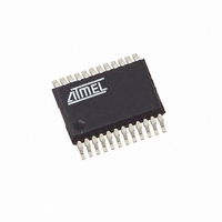
ATAM862P-TNSY3D Atmel, ATAM862P-TNSY3D Datasheet - Page 27

ATAM862P-TNSY3D
Manufacturer Part Number
ATAM862P-TNSY3D
Description
IC MCU FLASH 4K TX 315MHZ 24SSOP
Manufacturer
Atmel
Datasheet
1.ATAM862P-TNQY3D.pdf
(110 pages)
Specifications of ATAM862P-TNSY3D
Applications
UHF ASK/FSK
Core Processor
MARC4
Program Memory Type
FLASH (4 kB)
Controller Series
MARC4 4-Bit
Ram Size
256 x 4
Interface
SSI
Number Of I /o
11
Voltage - Supply
1.8 V ~ 4 V
Operating Temperature
-40°C ~ 125°C
Mounting Type
Surface Mount
Package / Case
24-SSOP
Processor Series
ATAM862x
Core
MARC4
Data Bus Width
4 bit
Mounting Style
SMD/SMT
Lead Free Status / RoHS Status
Lead free / RoHS Compliant
19.2
19.2.1
4554F–4BMCU–07/07
Oscillator Circuits and External Clock Input Stage
RC-oscillator 1 Fully Integrated
In this state an interrupt can wake up the controller with the RC-oscillator, and the external oscil-
lator can be activated and selected by software. A synchronization stage avoids too short clock
periods if the clock source or the clock speed is changed.
If an external input clock is selected, a supervisor circuit monitors the external input and gener-
ates a hardware reset if the external clock source fails or drops below 500 kHz for more than
1 ms.
Figure 19-1. Clock Module
Table 19-1.
The clock module generates two output clocks. One is the system clock (SYSCL) and the other
the periphery (SUBCL). The SYSCL can supply the core and the peripherals and the SUBCL
can supply only the peripherals with clocks. The modes for clock sources are programmable
with the OS1 bit and OS0 bit in the SC register and the CCS bit in the CM register.
The microcontroller block series consists of four different internal oscillators: two RC-oscillators,
one 4-MHz crystal oscillator, one 32-kHz crystal oscillator and one external clock input stage.
For timing insensitive applications, it is possible to use the fully integrated RC oscillator 1. It
operates without any external components and saves additional costs. The RC-oscillator 1 cen-
ter frequency tolerance is better than ±50% over the full temperature and voltage range. The
basic center frequency of the RC-oscillator 1 is f
default after power-on reset.
Mode
OSC1
OSC2
1
2
3
4
*
*
*
mask option
OS1
Oscin
Oscout
1
0
1
0
Clock Modes
Ext. clock
ExIn
RC oscillator2
R
4-MHz oscillator
Oscin
Oscout
32-kHz oscillator
Oscin
Oscout
Trim
OS0
SC:
1
1
0
0
BOT
RCOut2
RC-oscillator 1 (internal)
RC-oscillator 1 (internal)
RC-oscillator 1 (internal)
RC-oscillator 1 (internal)
ExOut
32Out
- - -
4Out
Stop
Stop
Stop
OS1
CCS = 1
OS0
Osc-Stop
Clock Source for SYSCL
Stop
oscillator 1
RC
CM:
RCOut1
Control
NSTOP
O
IN1
IN2
Sleep
WDL
≈ 3.8 MHz. The RC oscillator 1 is selected by
CCS
external trimming resistor
Cin
External input clock
RC-oscillator 2 with
CSS1
32-kHz oscillator
4-MHz oscillator
/2
CCS = 0
CSS0
/2
Divider
/2
ATAM862-3
32 kHz
Cin/16
/2
Clock Source for
SUBCL
32 kHz
C
C
C
in
in
in
/16
/16
/16
SYSCL
SUBCL
27


