E2FM-X2B1-M1 Omron, E2FM-X2B1-M1 Datasheet - Page 6
E2FM-X2B1-M1
Manufacturer Part Number
E2FM-X2B1-M1
Description
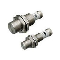
Proximity Sensors PNP M12 body M12 DC3 wire
Manufacturer
Omron
Series
E2FMr
Datasheet
1.E2FM-X5B1-M1.pdf
(12 pages)
Specifications of E2FM-X2B1-M1
Maximum Operating Temperature
+ 70 C
Supply Voltage
10 V to 30 V
Mounting Style
Panel
Sensing Distance
2 mm
Minimum Operating Temperature
- 25 C
Features
NO
Sensor Type
Inductive
Sensing Object
Metallic
Response Frequency
100Hz
Material - Body
Stainless Steel
Shielding
Shielded
Voltage - Supply
10 V ~ 30 V
Output Type
PNP-NO
Terminal Type
Connector
Package / Case
Cylinder, Threaded - M8
Lead Free Status / Rohs Status
Lead free / RoHS Compliant


DC 3-Wire (E2FM-X@C@, E2FM-X@B@)
*1. The response frequency of the DC switching section is an average value. Measurement conditions are as follows: standard sensing object, a distance of twice the
*2. NC (normally closed) models are also available. Contact your OMRON representative.
Item
Sensing distance
Set distance
Differential travel
Sensing object
Standard sensing object Iron, 8 × 8 × 1 mm
Response frequency *1
Power supply voltage
(operating voltage
range)
Current consumption
Output configuration
Control
output
Indicators
Operation mode
(with sensing object
approaching)
Protection circuits
Ambient temperature
range
Ambient humidity range Operating/Storage: 35% to 95% (with no condensation)
Temperature
influence
Voltage influence
Insulation resistance
Dielectric strength
Vibration resistance
Shock resistance
Degree of protection
Connection method
Weight
(packed
state)
Materi-
als
Accessories
standard sensing object, and a set distance of half the sensing distance.
Switching ca-
pacity
Residual
voltage
Pre-wired
Models (2 m)
Pre-wired
Connector
Models
Case
Sensing sur-
face
(thickness)
Clamping
nuts
Toothed
washer
Shielded
Model
Size
1.5 mm±10%
0 to 1.05 mm
15% max. of sensing distance
Ferrous metal (The sensing distance decreases with non-ferrous metal. Refer to Engineering Data on page 7.)
200 Hz
12 to 24 VDC (10 to 30 VDC), ripple (p-p): 10% max.
10 mA max.
PNP open collector output
200 mA max.
2 V max. (Load current: 200 mA, Cable length: 2 m)
Operation indicator (yellow LED)
C1 Models: NPN open collector, NO (normally open) *2
B1 Models: PNP open collector, NO (normally open) *2
Reversed power supply polarity protection, Surge suppressor, Load short-circuit protection, and Reversed output po-
larity protection (except the E2FM-X1R5B1-M1)
Operating/Storage: −25 to 70°C (with no icing or condensation)
±20% max. of sensing distance at 23°C in the temperature range of −25 to 70°C.
±1% max. of sensing distance in the rated voltage ±15% range (using the sensing distance at the rated voltage as
standard)
50 MΩ min. (at 500 VDC) between current-carrying parts and case
1,000 VAC, 50/60 Hz for 1 minute between current-carrying parts and case
Destruction: 10 to 55 Hz, 1.5-mm double amplitude for 2 hours each in X, Y, and Z directions
Destruction: 500 m/s
10 times each in X, Y, and Z
directions
IEC 60529 IP67
Unmarked: Pre-wired Models (Standard cable length: 2 m)
Models ending with -M1: Connector Models
---
Approx. 45 g
Stainless steel (SUS303)
Stainless steel (SUS303)
(0.4 mm)
Stainless steel (SUS303)
Zinc-plated iron
Instruction manual
E2FM-X1R5@
M8
2
2 mm±10%
0 to 1.4 mm
Iron, 12 × 12 × 1 mm
100 Hz
Destruction: 1,000 m/s
Approx. 170 g
Approx. 55 g
(0.8 mm)
E2FM-X2@
M12
2
Shielded
10 times each in X, Y, and Z directions
5 mm±10%
0 to 3.5 mm
Iron, 30 × 30 × 1 mm
100 Hz
Approx. 190 g
Approx. 75 g
E2FM-X5@
M18
10 mm±10%
0 to 7 mm
Iron, 54 × 54 × 1 mm
50 Hz
Approx. 275 g
Approx. 160 g
E2FM-X10@
M30
E2FM
6
Related parts for E2FM-X2B1-M1
Image
Part Number
Description
Manufacturer
Datasheet
Request
R

Part Number:
Description:
Proximity Sensors PNP M18 body M12 DC3 wire
Manufacturer:
Omron
Datasheet:
Part Number:
Description:
Proximity Sensors PNP M8 body M12 DC3 wire
Manufacturer:
Omron
Datasheet:
Part Number:
Description:
Proximity Sensors DC3 wire PNP M30 bod y M12conn
Manufacturer:
Omron
Datasheet:


Part Number:
Description:
PROX PLASTIC M8,1.5mm NPN(COO)
Manufacturer:
Omron
Datasheet:
Part Number:
Description:
PROX PLASTIC M30,10mm NPN-NC
Manufacturer:
Omron
Datasheet: