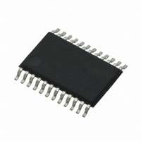
CS4270-DZZ Cirrus Logic Inc, CS4270-DZZ Datasheet - Page 5

CS4270-DZZ
Manufacturer Part Number
CS4270-DZZ
Description
IC CODEC 24BIT 105DB 24TSSOP
Manufacturer
Cirrus Logic Inc
Type
Stereo Audior
Specifications of CS4270-DZZ
Data Interface
Serial
Resolution (bits)
24 b
Number Of Adcs / Dacs
2 / 2
Sigma Delta
Yes
Dynamic Range, Adcs / Dacs (db) Typ
105 / 105
Voltage - Supply, Analog
3.1 V ~ 5.25 V
Voltage - Supply, Digital
3.1 V ~ 5.25 V
Operating Temperature
-40°C ~ 85°C
Mounting Type
Surface Mount
Package / Case
24-TSSOP
Audio Codec Type
Stereo
No. Of Adcs
1
No. Of Dacs
1
No. Of Input Channels
3
No. Of Output Channels
3
Adc / Dac Resolution
24bit
Sampling Rate
216kSPS
Ic Interface Type
I2C
Lead Free Status / RoHS Status
Lead free / RoHS Compliant
For Use With
598-1002 - BOARD EVAL FOR CS4270 CODEC
Lead Free Status / RoHS Status
Lead free / RoHS Compliant, Lead free / RoHS Compliant
Other names
598-1622
Available stocks
Company
Part Number
Manufacturer
Quantity
Price
Company:
Part Number:
CS4270-DZZ
Manufacturer:
CIRRUS
Quantity:
9
Company:
Part Number:
CS4270-DZZ
Manufacturer:
CIRRUS
Quantity:
62
CS4270
Figure 19. CS4270 Recommended Analog Output Filter .......................................................................... 30
Figure 20. Suggested Active-Low Mute Circuit ......................................................................................... 31
Figure 21. Control Port Timing, SPI Mode ................................................................................................ 32
Figure 22. Control Port Timing, I²C Mode ................................................................................................. 33
Figure 23. De-Emphasis Curve ................................................................................................................. 39
Figure 24. DAC Single-Speed Stopband Rejection .................................................................................. 41
Figure 25. DAC Single-Speed Transition Band ......................................................................................... 41
Figure 26. DAC Single-Speed Transition Band (detail) ............................................................................. 41
Figure 27. DAC Single-Speed Passband Ripple ....................................................................................... 41
Figure 28. DAC Double-Speed Stopband Rejection ................................................................................. 41
Figure 29. DAC Double-Speed Transition Band ....................................................................................... 41
Figure 30. DAC Double-Speed Transition Band (detail) ........................................................................... 42
Figure 31. DAC Double-Speed Passband Ripple ..................................................................................... 42
Figure 32. DAC Quad-Speed Stopband Rejection .................................................................................... 42
Figure 33. DAC Quad-Speed Transition Band .......................................................................................... 42
Figure 34. DAC Quad-Speed Transition Band (detail) .............................................................................. 42
Figure 35. DAC Quad-Speed Passband Ripple ........................................................................................ 42
Figure 36. ADC Single-Speed Stopband Rejection .................................................................................. 43
Figure 37. ADC Single-Speed Stopband (detail) ...................................................................................... 43
Figure 38. ADC Single-Speed Transition Band (detail) ............................................................................. 43
Figure 39. ADC Single-Speed Passband Ripple ....................................................................................... 43
Figure 40. ADC Double-Speed Stopband Rejection ................................................................................. 43
Figure 41. ADC Double-Speed Stopband (detail) ..................................................................................... 43
Figure 42. ADC Double-Speed Transition Band (detail) ........................................................................... 44
Figure 43. ADC Double-Speed Passband Ripple ..................................................................................... 44
Figure 44. ADC Quad-Speed Stopband Rejection .................................................................................... 44
Figure 45. ADC Quad-Speed Stopband (detail) ........................................................................................ 44
Figure 46. ADC Quad-Speed Transition Band (detail) .............................................................................. 44
Figure 47. ADC Quad-Speed Passband Ripple ........................................................................................ 44
LIST OF TABLES
Table 1. Speed Modes .............................................................................................................................. 22
Table 2. Clock Ratios - Stand-Alone Mode ............................................................................................... 23
Table 3. CS4270 Stand-Alone Mode Control............................................................................................ 24
Table 4. Speed Modes .............................................................................................................................. 25
Table 5. Clock Ratios - Control Port Mode................................................................................................ 25
Table 6. Analog Input Design Parameters ................................................................................................ 29
Table 7. Memory Address Pointer............................................................................................................. 33
Table 8. Functional Mode Selection.......................................................................................................... 36
Table 9. MCLK Divider Configuration........................................................................................................ 36
Table 10. DAC Digital Interface Formats .................................................................................................. 37
Table 11. ADC Digital Interface Formats .................................................................................................. 37
Table 12. Soft Cross or Zero Cross Mode Selection................................................................................. 38
Table 13. Digital Volume Control .............................................................................................................. 40
DS686PP1
5


