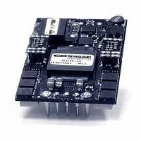
SLC100-9 Murata Power Solutions Inc, SLC100-9 Datasheet - Page 5

SLC100-9
Manufacturer Part Number
SLC100-9
Description
DC/DC Converters & Regulators 36~75V to 12V 8.3A Positive Logic
Manufacturer
Murata Power Solutions Inc
Series
SLC100-9r
Datasheet
1.SLC100-27.pdf
(9 pages)
Specifications of SLC100-9
Product
Isolated
Output Power
100 W
Input Voltage Range
36 V to 75 V
Input Voltage (nominal)
48 V
Number Of Outputs
1
Output Voltage (channel 1)
12 V
Output Current (channel 1)
8.3 A
Isolation Voltage
2 KV
Package / Case Size
Quarter Brick
Lead Free Status / Rohs Status
Lead free / RoHS Compliant
Remote Sense
The remote sense feature of the SLC100 can be used
to compensate for voltage drops in the output power
lines by sensing output voltage directly at the point of
load. To enable this feature, connect the +Sense and
–Sense pins to the +Vout and –Vout pins, respectively,
at the point in the circuit where the tightest regulation
is required (Figure 1). The sense leads conduct very
little current compared with the power leads and there-
fore provide a more accurate indication of load voltage
for regulation purposes. This enables the converter to
increase (or decrease) its output voltage to compensate
for any load distribution losses, allowing for a more
precise load voltage. Refer to the product data sheet
for the maximum output voltage compensation range of
In general, the line resistance, or load drop, between
the output pins of the converter and load should be
minimized. Using remote sense, a large line resistance,
with a regulated load voltage, will result in a higher
output voltage at the output of the DC/DC Converter. To
prevent exceeding the converter’s output power limits,
a higher output voltage will require a reduction in the
maximum allowable output current in accordance with
the voltage/current power relationship. To minimize
the line resistance between the converter and the load,
the converter should be placed as close to the load as
possible. Line resistance can further be decreased by
using heavy gauge wire or by increasing the cross sec-
tional area of the PC board traces.
Figure 1 – Remote Sensing
+ Vin
ON/OFF
- Vin
(Top View)
SLC100
+ Sense
-
+ Vout
Sense
- Vout
Trim
APPLICATION NOTES
Load
C
C
B
B
•
•
SLC100 Rev B
C
L
Output Voltage Trim
The SLC100’s output voltage may be adjusted high or
low by an amount indicated on the product data sheet.
As shown in Figure 2, to raise the converter’s output
voltage a resistor must be placed between the Trim pin
and +Vout pin.
When using remote sense with dynamic loads, the
transient response at the point of load may be limited
by the inductance present in the power lines. Severe
load steps may require the addition of a capacitor C
across the output lines. When the load demands an
immediate increase in load current, this capacitor helps
to supply a portion of the current and reduces the bur-
den on the converter.
If remote sensing is not desired then +Sense and
-Sense must be tied to their respective outputs for
proper operation.
When the load is physically distanced from the con-
verter, the inductance of the power leads, and any by-
pass conductance at the load, can result in increased
phase shift in the converter’s feedback loop, causing
instability. This situation can be eliminated by inserting
bypass capacitors (C
leads directly at the output pins. These capacitors de-
couple any AC on the power lines and assure that only
the DC voltage is sensed.
5/2004
+ Vin
ON/OFF
- Vin
Figure 2 – Trim Up Circuit
SLC100
(Top View)
B
) from the outputs to the sense
+ Sense
-
+ Vout
- Vout
Sense
Trim
R
Load
T
L
5


