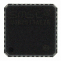
USB2513-AEZG SMSC, USB2513-AEZG Datasheet - Page 41

USB2513-AEZG
Manufacturer Part Number
USB2513-AEZG
Description
IC USB 2.0 3PORT HUB CTLR 36-QFN
Manufacturer
SMSC
Datasheet
1.USB2512B-AEZG.pdf
(76 pages)
Specifications of USB2513-AEZG
Controller Type
USB 2.0 Controller
Interface
Serial EEPROM
Voltage - Supply
3 V ~ 3.6 V
Operating Temperature
0°C ~ 70°C
Mounting Type
Surface Mount
Package / Case
36-QFN
Lead Free Status / RoHS Status
Lead free / RoHS Compliant
Current - Supply
-
Other names
638-1052-6
Available stocks
Company
Part Number
Manufacturer
Quantity
Price
Company:
Part Number:
USB2513-AEZG
Manufacturer:
SMSC
Quantity:
2 492
Part Number:
USB2513-AEZG
Manufacturer:
SMSC
Quantity:
20 000
USB 2.0 Hi-Speed Hub Controller
Datasheet
SMSC USB251x
8.2.1.11
8.2.1.12
NUMBER
NUMBER
BIT
BIT
7:0
7:0
Register 0Ah: Port Disable For Self-Powered Operation
Register 0Bh: Port Disable For Bus-Powered Operation
PORT_DIS_SP
PORT_DIS_BP
BIT NAME
BIT NAME
Port Disable Self-Powered: Disables 1 or more ports.
0 = Port is available
1 = Port is disabled
During self-powered operation when mapping mode is disabled
(PRTMAP_EN='0'), this selects the ports which will be permanently disabled,
and are not available to be enabled or enumerated by a host controller. The
ports can be disabled in any order, the internal logic will automatically report
the correct number of enabled ports to the USB host, and will reorder the
active ports in order to ensure proper function.
When using the internal default option, the PRT_DIS_P[x:1] and
PRT_DIS_M[x:1] pins will disable the appropriate ports.
Bit 7= Controls Port 7
Bit 6= Controls Port 6
Bit 5= Controls Port 5
Bit 4= Controls Port 4
Bit 3= Controls Port 3
Bit 2= Controls Port 2
Bit 1= Controls Port 1
Bit 0= Reserved, always = ‘0’
Port Disable Bus-Powered: Disables 1 or more ports.
0 = Port is available
1 = Port is disabled
During self-powered operation when mapping mode is disabled
(PRTMAP_EN='0'), this selects the ports which will be permanently disabled,
and are not available to be enabled or enumerated by a host Controller. The
ports can be disabled in any order, the internal logic will automatically report
the correct number of enabled ports to the USB host, and will reorder the
active ports in order to ensure proper function.
When using the internal default option, the PRT_DIS_P[x:1] and
PRT_DIS_M[x:1] pins will disable the appropriate ports.
Bit 7= Controls Port 7
Bit 6= Controls Port 6
Bit 5= Controls Port 5
Bit 4= Controls Port 4
Bit 3= Controls Port 3
Bit 2= Controls Port 2
Bit 1= Controls Port 1
Bit 0 is Reserved, always = ‘0’
DATASHEET
41
DESCRIPTION
DESCRIPTION
Revision 1.1 (04-26-10)


