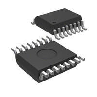
MIC2012-1PZQS TR Micrel Inc, MIC2012-1PZQS TR Datasheet

MIC2012-1PZQS TR
Specifications of MIC2012-1PZQS TR
MIC2012-1PZQSTR
Related parts for MIC2012-1PZQS TR
MIC2012-1PZQS TR Summary of contents
Page 1
... MIC2012 General Description The MIC2012 is a dual channel USB power switch designed to support the power distribution requirements for USB Wakeup from the ACPI S3 state. The MIC2012 will directly switch its two outputs between a 5V main supply and a 5V auxiliary supply normally provided in ATX style power supplies. ...
Page 2
... MIC2012 Ordering Information Part Number Standard Pb-Free (1) (1) MIC2012BM MIC2012YM MIC2012CM MIC2012ZM MIC2012PCM MIC2012PZM MIC2012-1PCQS MIC2012-1PZQS MIC2012-2PCQS MIC2012-2PZQS MIC2072-1PCQS MIC2072-2PZQS MIC2072-2PCQS MIC2072-2PZQS Note: 1. Contact factory for availablity Pin Confi guration FAULT1 1 S3# 2 AUX 3 GND 4 8-Pin SOIC (M) MIC2012/2072 Enable Fault Output ...
Page 3
... MAIN 5V Main Supply (Input): All MAIN inputs must be connected together exter- nally. OUT1 Channel 1 (Output): For MIC2012-1, -2 both pins must be externally con- nected together. EN2 Enable (Input): Channel 2, active-high (–1) or active-low (–2). Toggling this input also resets the latched output of the MIC2072. ...
Page 4
... EN2, for MIC20x2-x only) I S3#, EN1, EN2 Input Current IN (EN1, EN2, for MIC20x2-x only) I OUT1, OUT2 Leakage Current OFF (MIC2012-x, MIC2072-x only) Pull-Up Current During Latched Output State (MIC2072-1, -2) MIC2012/2072 Operating Ratings (Note 1, Note 4) Supply Voltage (V Ambient Temperature (T Junction Temperature (T Package Thermal Resistance QSOP (θ ...
Page 5
... For MIC20x2-2(P) OFF occurs when Micrel Min Typ Max Units 1.95 V 0.4 V/s 140 °C 120 °C 160 °C 150 °C 0 0.2 10 µ µs 2 µ µ µs 0.6 ms 120 µs 0.5 ms 115 µ 7.5 ms > 2.4V and 40ms max if one channel DLY MIC2012/2072 ...
Page 6
... MIC2012 Timing Diagrams OUT OUT V OUT I OUT FAULT# MAIN S3# MIC2012/2072 50 90% Figure 2. MIC2012/72-1 50 90% Figure 3. MIC2012/72-2 Output shorted to ground I LIMIT DLY Figure 4. Overcurrent Response Timing t H 1.5V Figure 5. MAIN to S3# Timing 6 10% 10 1.5V January 2005 Micrel ...
Page 7
... MIC2012 Test Circuit V OUT January 2005 V OUT I Device OUT Under OUT Test 90% 90% 10% 10% 7 Micrel t f MIC2012/2072 ...
Page 8
... V AUX 1.6 4.5 V AUX 1 4.5, 5.0, 5.5V AUX V = S3# = 5.0V MAIN 1.2 -40 - 100 TEMPERATURE (°C) Enable Threshold (decreasing) vs. Temperature ( MIC2012-1/-2) 2.0 4.5V 1.8 MAIN 1.6 5.0V MAIN 1.4 5.5V MAIN 1 4.5V to 5.5V MAIN V = S3# = 5.0V AUX 1.0 -40 - 100 TEMPERATURE (°C) ...
Page 9
... MIC2012 Output Reset Threshold vs. Temperature 3.00 (Output Latched Off –MIC2072) V Rising OUT 2. 5.0 V MAIN V = S3# = 4.5, 5.0, 5.5V AUX 2.50 5.5V AUX 2.25 2.00 5.0V 1.75 AUX 4.5V AUX 1.50 -40 - 100 TEMPERATURE (°C) January 2005 9 Micrel MIC2012/2072 ...
Page 10
... LOAD TIME (500s/div) Main Start-up by UVLO & V ramp from MAIN AUX MAIN AUX S3 [ON 3.20V LOAD LOAD TIME (500s/div) Main Turn-On Response EN toggles from [OFF] to [ON] TIME (250s/div) MIC2012/2072 = 5V AUX C = 100F =5V MAIN AUX S3 LOAD LOAD 10 AUX Shutdown by UVLO 2.96V V ramps from ...
Page 11
... AUX MAIN EN toggles from [ON] to [OFF] R LOAD C LOAD TIME (100s/div) Turn-Off from AUX to S3# V =5V AUX MAIN S3# toggles from [LO] to [HI [ON LOAD LOAD TIME (1ms/div) Main-Ramped to Short by MOSFET 1. =5V MAIN AUX = 1F LOAD toggles from > <0.5 LOAD TIME (50ms/div) Micrel = MIC2012/2072 ...
Page 12
... MAIN RL toggles from >1k to <0.5 OAD LOAD TIME (25ms/div) AUX Turn-On into Short V EN toggles from [OFF] to [ON] TIME (2.5ms/div) AUX Inrush Current into Small toggles from [OFF] to [ON] TIME (100s/div) MIC2012/2072 V =5V AUX = S3 MAIN C = 100F LOAD LOAD V =5V AUX = S3 MAIN I < ...
Page 13
... MIC2012 January 2005 AUX-to-Main Cross Conduction =5V MAIN AUX S3# toggles from [LO] to [HI [ON LOAD LOAD 3.96ms TIME (1ms/div) 13 Micrel MIC2012/2072 ...
Page 14
... MOSFET switch from the AUX input to each of its two outputs. Conversely when the S3# input is HIGH (S0 state) the MIC2012/72 will switch a 100mΩ, 500mA MOSFET switch from the MAIN input to each of its two outputs. The lower current limit during the ACPI S3 state helps to ensure that the standby supply maintains regulation even during fault conditions ...
Page 15
... This helps to ensure that the power supply , has DLY Thermal Shutdown Figure 6. MIC2012 System Timing Load Removed– Figure 7. MIC2072 System Timing— Output Resets When Load is Removed 15 is typically 10ms. ...
Page 16
... A Purchaser's use or sale of Micrel Products for use in life support appliances, devices or systems is a Purchaser's own risk and Purchaser agrees to fully indemnify MIC2012/2072 16-Pin QSOP (QS) ...


