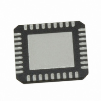
USB2513B-AEZG SMSC, USB2513B-AEZG Datasheet - Page 26

USB2513B-AEZG
Manufacturer Part Number
USB2513B-AEZG
Description
IC USB 2.0 3PORT HUB CTLR 36QFN
Manufacturer
SMSC
Datasheet
1.USB2512B-AEZG.pdf
(76 pages)
Specifications of USB2513B-AEZG
Controller Type
USB 2.0 Hub Controller
Interface
I²C EEPROM, SMBus (2-Wire, I²C)
Voltage - Supply
3 V ~ 3.6 V
Current - Supply
65mA
Operating Temperature
0°C ~ 85°C
Mounting Type
Surface Mount
Package / Case
36-VQFN Exposed Pad, 36-HVQFN, 36-SQFN, 36-DHVQFN
Lead Free Status / RoHS Status
Lead free / RoHS Compliant
Other names
638-1101
Available stocks
Company
Part Number
Manufacturer
Quantity
Price
Company:
Part Number:
USB2513B-AEZG
Manufacturer:
MICROCHIP
Quantity:
1 000
Part Number:
USB2513B-AEZG
Manufacturer:
SMSC
Quantity:
20 000
USB 2.0 Hi-Speed Hub Controller
Datasheet
Table 5.2 USB251x Pin Descriptions (continued)
BUFFER
SYMBOL
TYPE
DESCRIPTION
MISC
XTALIN
ICLKx
Crystal Input
24 MHz crystal
This pin connects to either one terminal of the crystal or to an external
24 MHz clock when a crystal is not used.
CLKIN
External Clock Input
This pin connects to either one terminal of the crystal or to an external
24 MHz clock when a crystal is not used.
XTALOUT
OCLKx
Crystal Output
24 MHz crystal
This is the other terminal of the crystal, or a no connect pin, when an external
clock source is used to drive XTALIN/CLKIN.
SUSP_IND /
I/O
Active/Suspend status LED
Suspend Indicator: Indicates USB state of the hub.
‘negated’ = Unconfigured, or configured and in USB Suspend
‘asserted’ = the hub is configured, and is active (i.e., not in suspend)
LOCAL_PWR /
Local Power: Detects availability of local self-power source.
Low = Self/local power source is NOT available (i.e., the hub gets all power
from Upstream USB VBus).
High = Self/local power source is available.
NON_REM[0]
NON_REM[0] Strap Option:
If this strap is enabled by package and configuration settings (see
Table 8.1,
"Hub Configuration
Options"), this pin will be sampled (in conjunction with
NON_REM[1]) at RESET_N negation to determine if ports [x:1] contain
permanently attached (non-removable) devices. Also, the active state of the
LED will be determined as follows:
NON_REM[1:0] = ‘00’, All ports are removable, and the LED is active high
NON_REM[1:0] = ‘01’, Port 1 is non-removable, and the LED is active low
NON_REM[1:0] = ‘10’, Ports 1 & 2 are non-removable, and the LED is active
high
NON_REM[1:0] = ‘11’, When available, ports 1, 2 & 3 are non-removable, and
the LED is active low
TEST
IPD
TEST pin
User must treat as a no connect pin or connect to ground. No trace or signal
should be routed or attached to this pin.
Revision 1.1 (04-26-10)
26
SMSC USB251x
DATASHEET


