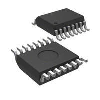
MIC2010-1PCQS Micrel Inc, MIC2010-1PCQS Datasheet - Page 3

MIC2010-1PCQS
Manufacturer Part Number
MIC2010-1PCQS
Description
IC USB PWR CTRLR DUAL 16-QSOP
Manufacturer
Micrel Inc
Datasheet
1.MIC2010-1PBQS_TR.pdf
(13 pages)
Specifications of MIC2010-1PCQS
Controller Type
USB Power Controller
Interface
USB
Voltage - Supply
4.5 V ~ 5.5 V
Current - Supply
1mA
Operating Temperature
0°C ~ 70°C
Mounting Type
Surface Mount
Package / Case
16-QSOP
Lead Free Status / RoHS Status
Contains lead / RoHS non-compliant
Pin Description
January 2005
MIC2010/2070
Pin Number
11, 12
13, 14
9, 10
15
16
1
2
3
4
5
6
7
8
Pin Name
FAULT1
FAULT2
RSET1
RSET2
OUT2
OUT1
MAIN
GND
AUX
EN1
EN2
S3#
NC
Pin Function
Fault Status (Output): Channel 1, active-low; weak pull-up to AUX. FAULT1
is asserted LOW when channel 1 is in a thermal shutdown state or overcur-
rent condition for more than 5ms. MIC2070 latches this output in its asserted
state upon overcurrent condition. Toggling EN1 or removing the load will
reset the circuit breaker latch, and deassert FAULT1.
Enable (Input): Channel 1, active-high (–1) or active-low (–2). Toggling this
input also resets the latched output of the MIC2070.
Control (Input): When this input is high, the MAIN inputs are connected to
OUT1 and OUT2 via 100mΩ, 500mA MOSFET switches. When this input is
LOW, the AUX inputs are connected to OUT1 and OUT2 via 500mΩ
MOSFET switches with a current-limit threshold specified by external
resistors, RSET1 and RSET2.
Current-Limt Set Resistor (Input): Channel 1. A resistor connected to this
input sets the current-limit threshold in AUX mode (S3# asserted). The
current-limit threshold is determined by approximately 18/RSET1.
Auxiliary 5V Supply (Input): Also used as power supply for internal circuitry.
No Connection: This pin may be connected to other pins without restriction.
Current-Limit Set Resistor (Input): Channel 2. A resistor connected to this
input sets the current-limit threshold in AUX mode (S3# asserted). The
current-limit threshold is determined by approximately 18/RSET2.
Ground
Channel 2 (Output): Both pins must be connected together externally.
5V Main Supply (Input): All MAIN inputs must be connected together
externally.
Channel 1 (Output): Both pins must be connected together externally.
Enable (Input): Channel 2, active-high (–1) or active-low (–2). Toggling this
input also resets the latched output for the MIC2070.
Fault Status (Output): Channel 2, active-low; weak pull-up to AUX. FAULT2
is asserted LOW when channel 2 is in a thermal shutdown state or overcur-
rent condition for more than 5ms. MIC2070 latches this output in it's asserted
state upon overcurrent condition. Toggling EN2 or removing load will reset
the circuit breaker latch, and deassert FAULT2.
3
M9999-101104
Micrel


