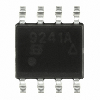
A series of compact, single-ended bus drivers for automotive
diagnostic applications enables communication over the
relatively long distances between testing equipment and
automotive electronic control units, while protecting sensitive
logic devices from the hazards of the automotive environment.
The Si9241AEY and Si9243EY are the first narrow-body, small
outline products on the market to meet the ISO 9141 standard for
this application.
ISO 9141 is an international standard for communications
between automobiles and diagnostic testers. It specifies a serial
data communication bus between the vehicle’s Electronic Control
Units (ECUs) and the diagnostic test SAE OBDII Scan Tool (SAE
J 1978). ISO 9141 has been adopted by the California Air
Resources Board for all cars sold in California with feedback fuel
control systems. Similar rules are being adopted in New York,
New Jersey, Massachusetts, and Maryland, and are expected to
affect the design of most cars sold in the United States.
Figure 1 is a system configuration for the ISO 9141 specification.
The primary form of communication is with the single-ended
K-Line. The K-Line passes data bidirectionally, as well as
transferring all address information during initialization.
The optional L-Line is unidirectional and is only used to pass
address information from the diagnostic tester to the ECUs during
initialization. The L-Line is in a 1-state during all other events. The
K-Line will mimic the L-Line’s address initialization.
Document Number: 70573
16-Jan-01
ECU 1
FIGURE 1. Possible System Configuration
Driver ICs for Automotive Diagnostic Communications
Connector According to
ECU 2
SAE J1978
Arrows indicate direction
of data flow.
L
K
Meet ISO 9141 Standards
Diagnostic Tester
According to
SAE J1978
Vishay Siliconix ISO 9141 Drivers
Vishay Siliconix has produced two drivers to meet ISO 9141
configurations. Each driver is housed in a small-outline
surface-mount package with on-board fault protection to protect
the controller and tester from the automotive environment.
Both drivers have short circuit and over-temperature protection
and open load detection. The devices protect against voltage
transients ( –3 V
9141 (–1 V to 40 V).
The Drivers
The Si9241AEY (Figure 2) is designed for the user that needs
only K-Line communication. The ECU controls the K output
through Transmit Pin (Tx) and Chip Select Bar (CS). The fault
detection circuitry monitors Tx and K to determine open and
shorted loads. If K is high when Tx is low, the K-Line is shorted.
Conversely, if K is low when Tx is high, the K-Line is open.
Over-temperature protection is always enabled, so a fault is
determined whenever the junction temperature exceeds 150_C.
All faults are latched until chip select bar is set high.
If chip select is not to be used, TX and CS Bar should be tied
together, so all faults will reset when TX toggles high.
The Si9243EY (Figure 3) is designed for users that need both K
and L Lines for communication. It is packaged in an SO-8 for
space savings, but due to pin limitation, it does not have a chip
select function. For the same reason, the Fault Detection signal
is not bonded out. The fault detection and protection circuitry are
active, and the device will shut down in the event of a fault.
FAULT
RX
CS
TX
FIGURE 2. Si9241A K-Line Only Driver
V
DD
3
V
[V
DD
BAT
, K and L] v 45 V), which exceed ISO
Detector
Fault
Vishay Siliconix
GND
V
+
B
–
www.vishay.com
AN602
V
2
B
K
1


