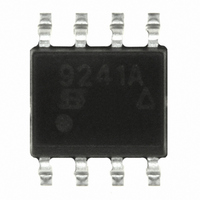
SI9241AEY-T1-E3 Vishay, SI9241AEY-T1-E3 Datasheet - Page 3

SI9241AEY-T1-E3
Manufacturer Part Number
SI9241AEY-T1-E3
Description
IC SINGLE-ENDED BUS TXRX 8-SOIC
Manufacturer
Vishay
Type
Transceiverr
Specifications of SI9241AEY-T1-E3
Logic Type
Single-Ended Bus Transceiver
Number Of Drivers/receivers
1/1
Voltage - Supply
4.5 V ~ 5.5 V
Mounting Type
Surface Mount
Package / Case
8-SOIC (3.9mm Width)
Number Of Channels Per Chip
1
Output Level
CMOS, LSTTL
Output Type
Open Drain
Supply Voltage (max)
36 V
Supply Voltage (min)
6 V
Maximum Operating Temperature
+ 125 C
Minimum Operating Temperature
- 40 C
Mounting Style
SMD/SMT
No. Of Channels
1
Input Level
3.5V
Logic Case Style
SOIC
No. Of Pins
8
Supply Voltage Range
4.5V To 5.5V
Operating Temperature Range
-40°C To +125°C
Lead Free Status / RoHS Status
Lead free / RoHS Compliant
Protocol
-
Lead Free Status / Rohs Status
Lead free / RoHS Compliant
Other names
SI9241AEY-T1-E3TR
Available stocks
Company
Part Number
Manufacturer
Quantity
Price
Company:
Part Number:
SI9241AEY-T1-E3
Manufacturer:
KEMET
Quantity:
1 001
Part Number:
SI9241AEY-T1-E3
Manufacturer:
VISHAY/威世
Quantity:
20 000
Physical Layer
Figure 5 shows the physical layer capacitance of the ISO 9141
communication scheme.
where C
equal to 2 nF.
The capacitance of the K or L Lines with respect to GND can be
no greater than 500 pF.
The resistance of the K and L Line is specified with respect to their
State.
Any resistance placed between the K or L Line and V
a value greater than 100 kW.
Data Rate
The maximum data rate will vary depending on the number of
ECUs and length of cabling. ISO 9141 specifies a maximum bus
capacitance of 9.6 nF. Figure 6 shows the maximum data rate
versus capacitance.
Data Format and Protocol
This application note will only give a general outline of the ISO
9141 communication scheme. The user is advised to read the
actual ISO 9141 specification.
Document Number: 70573
16-Jan-01
C
C
C
TE
OBW
ECU
Reading
“1”
“0”
or
ECU
FIGURE 5. Communication Schematic
Vehicle (Clause 9)
= Tester and Cables
= On-Board Wiring
= Sum of all ECU Input Capacitance
+ C
K (ECU to GND)
L (ECU to GND)
OBW
ECU
V
C
ECU
is less or equal to 7.6 nF and C
B
C
ECU
Line K
GND
Diagnostic Tester
C
TE
(Clause 8)
w 50 kW v 110 W
I
w 50 kW N/A
Reading
b
TE
must have
“1”
“0”
or
is less or
Initialization
Before initialization, the K-Line is a Logic 1 for the time period of
the address to be transmitted. The diagnostic tester then sends
an 8-bit address on the K and L lines (one start, 8-bit address, one
stop) to the ECU.
Transmission
Before transmitting, the K-Line is a Logic 1 for the time period of
the word to be transmitted. An alternate bit pattern is then sent to
synchronize the receiver and set the baud rate. After the
transmission of the synchronization pattern, two key words are
sent to the tester to identify the form of the data and the hardware
configuration.
When the last key word is sent by the ECU, the tester will echo
back the logic inversion of the last word back to the ECU. When
this is complete, the ECU will transmit the logic inversion of the
initialization address.
Conclusion
Vishay Siliconix’ ISO 9141 bus driver series is produced to save
the automotive designer time and space while improving the
overall reliability of the diagnostic system. Each driver exceeds
the ISO 9141 transient and data requirements, as well saving
significant space overall to a discrete solution. With these factors
considered, it should reduce manufacturing, building and design
costs, and produce a very economical solution to automotive bus
interfacing.
Reference
ISO 9141 - CARB Road Vehicles * Diagnostic Systems.
N425/rev. Jan. 91
FIGURE 6. Maximum NRZ Data Rate with Capacitive
1000
100
0.1
10
1
1
Load Si924X with 510-W Load
10
Capacitance (nF)
Assumes V
and a capacitive load
100
Vishay Siliconix
BAT
above 9 V,
1000
www.vishay.com
AN602
10,000
3


