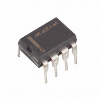
MAX13085EEPA+ Maxim Integrated Products, MAX13085EEPA+ Datasheet - Page 16

MAX13085EEPA+
Manufacturer Part Number
MAX13085EEPA+
Description
IC TXRX RS485/422 8-DIP
Manufacturer
Maxim Integrated Products
Type
Transceiverr
Datasheet
1.MAX13082ECSA.pdf
(24 pages)
Specifications of MAX13085EEPA+
Number Of Drivers/receivers
1/1
Protocol
RS422, RS485
Voltage - Supply
4.5 V ~ 5.5 V
Mounting Type
Through Hole
Package / Case
8-DIP (0.300", 7.62mm)
Lead Free Status / RoHS Status
Lead free / RoHS Compliant
The MAX13089E has several programmable operating
modes. Transmitter rise and fall times are programma-
ble, resulting in maximum data rates of 250kbps,
500kbps, and 16Mbps. To select the desired data rate,
drive SRL to one of three possible states by using a
three-state driver: V
250kbps operation, set the three-state device in high-
impedance mode or leave SRL unconnected. For
500kbps operation, drive SRL high or connect it to V
For 16Mbps operation, drive SRL low or connect it to
GND. SRL can be changed during operation without
interrupting data communications.
Occasionally, twisted-pair lines are connected backward
from normal orientation. The MAX13089E has two pins
that invert the phase of the driver and the receiver to cor-
rect this problem. For normal operation, drive TXP and
RXP low, connect them to ground, or leave them uncon-
nected (internal pulldown). To invert the driver phase,
drive TXP high or connect it to V
phase, drive RXP high or connect it to V
receiver threshold is positive when RXP is high.
The MAX13089E can operate in full- or half-duplex
mode. Drive H/F low, leave it unconnected (internal
pulldown), or connect it to GND for full-duplex opera-
+5.0V, ±15kV ESD-Protected, Fail-Safe,
Hot-Swap, RS-485/RS-422 Transceivers
Figure 9. Simplified Structure of the Driver Enable Pin (DE)
16
DE
______________________________________________________________________________________
TIMER
V
TIMER
CC
5kΩ
M1
100µA
500µA
10µs
CC
MAX13089E Programming
, GND, or unconnected. For
M2
CC
. To invert the receiver
SR LATCH
CC
. Note that the
DE
(HOT SWAP)
CC
.
tion. Drive H/F high for half-duplex operation. In full-
duplex mode, the pin configuration of the driver and
receiver is the same as that of a MAX13080E. In half-
duplex mode, the receiver inputs are internally connect-
ed to the driver outputs through a resistor-divider. This
effectively changes the function of the device’s outputs.
Y becomes the noninverting driver output and receiver
input, Z becomes the inverting driver output and receiver
input. In half-duplex mode, A and B are still connected to
ground through an internal resistor-divider but they are
not internally connected to the receiver.
As with all Maxim devices, ESD-protection structures
are incorporated on all pins to protect against electro-
static discharges encountered during handling and
assembly. The driver outputs and receiver inputs of the
MAX13080E family of devices have extra protection
against static electricity. Maxim’s engineers have devel-
oped state-of-the-art structures to protect these pins
against ESD of ±15kV without damage. The ESD struc-
tures withstand high ESD in all states: normal operation,
shutdown, and powered down. After an ESD event, the
MAX13080E–MAX13089E keep working without latchup
or damage.
ESD protection can be tested in various ways. The
transmitter outputs and receiver inputs of the
MAX13080E–MAX13089E are characterized for protec-
tion to the following limits:
• ±15kV using the Human Body Model
• ±6kV using the Contact Discharge method specified
ESD performance depends on a variety of conditions.
Contact Maxim for a reliability report that documents
test setup, test methodology, and test results.
Figure 10a shows the Human Body Model, and Figure
10b shows the current waveform it generates when dis-
charged into a low impedance. This model consists of a
100pF capacitor charged to the ESD voltage of interest,
which is then discharged into the test device through a
1.5kΩ resistor.
The IEC 61000-4-2 standard covers ESD testing and
performance of finished equipment. However, it does
not specifically refer to integrated circuits. The
MAX13080E family of devices helps you design equip-
ment to meet IEC 61000-4-2, without the need for addi-
tional ESD-protection components.
in IEC 61000-4-2
±15kV ESD Protection
ESD Test Conditions
Human Body Model
IEC 61000-4-2


