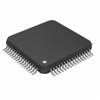
DS26521LN+ Maxim Integrated Products, DS26521LN+ Datasheet - Page 56

DS26521LN+
Manufacturer Part Number
DS26521LN+
Description
IC TXRX T1/E1/J1 64-LQFP
Manufacturer
Maxim Integrated Products
Type
Line Interface Units (LIUs)r
Datasheet
1.DS26521LN.pdf
(258 pages)
Specifications of DS26521LN+
Number Of Drivers/receivers
1/1
Protocol
T1/E1/J1
Voltage - Supply
3.135 V ~ 3.465 V
Mounting Type
Surface Mount
Package / Case
64-LQFP
Lead Free Status / RoHS Status
Lead free / RoHS Compliant
- Current page: 56 of 258
- Download datasheet (2Mb)
Table 8-21. E1 Line Code Violation Counting Options
8.9.9.2 Path Code Violation Count Register (PCVCR)
In T1 operation, the Path Code Violation Count register (PCVCR) records either Ft, Fs, or CRC-6 errors. When the
receive side of a framer is set to operate in the T1 ESF framing mode, PCVCR records errors in the CRC-6
codewords. When set to operate in the T1 D4 framing mode, PCVCR counts errors in the Ft framing bit position.
Via the ERCNT.2 bit, a framer can be programmed to also report errors in the Fs framing bit position. PCVCR is
disabled during receive loss of synchronization (RLOF = 1) conditions. See
exactly what errors the PCVCR counts in T1 operation.
In E1 operation, PCVCR records CRC-4 errors. Since the maximum CRC-4 count in a one-second period is 1000,
this counter cannot saturate. The counter is disabled during loss of sync at either the FAS or CRC-4 level; it
continues to count if loss of multiframe sync occurs at the CAS level.
The Path Code Violation Count Register 1 (PCVCR1) is the most significant word and Path Code Violation Count
Register 2 (PCVCR2) is the least significant word of a 16-bit counter that records path violations (PVs).
Table 8-22. T1 Path Code Violation Counting Arrangements
8.9.9.3 Frames Out of Sync Count Register (FOSCR)
The FOSCR is used to count the number of multiframes that the receive synchronizer is out of sync. This number is
useful in ESF applications needing to measure the parameters loss of frame count (LOFC) and ESF error events
as described in AT&T publication TR54016. When the FOSCR is operated in this mode, it is not disabled during
receive loss of synchronization (RLOF = 1) conditions. The FOSCR has an alternate operating mode whereby it will
count either errors in the Ft framing pattern (in the D4 mode) or errors in the FPS framing pattern (in the ESF
mode). When the FOSCR is operated in this mode, it is disabled during receive loss of synchronization (RLOF = 1)
conditions. See
In E1 mode, the FOSCR counts word errors in the frame alignment signal in time slot 0. This counter is disabled
when RLOF is high. FAS errors will not be counted when the framer is searching for FAS alignment and/or
synchronization at either the CAS or CRC-4 multiframe level. Since the maximum FAS word error count in a one-
second period is 4000, this counter cannot saturate.
The Frames Out of Sync Count Register 1 (FOSCR1) is the most significant word and Frames Out of Sync Count
Register 2 (FOSCR2) is the least significant word of a 16-bit counter that records frames out of sync.
Table 8-23. T1 Frames Out of Sync Counting Arrangements
E1 CODE VIOLATION SELECT
FRAMING MODE
FRAMING MODE
(RCR1.5)
ESF
D4
D4
ESF
ESF
D4
D4
(ERCNT.0)
0
1
Table 8-23
COUNT Fs ERRORS?
COUNT MOS OR F-BIT ERRORS
for a detailed description of what the FOSCR is capable of counting.
Don’t Care
Yes
No
(ERCNT.1)
MOS
MOS
F-Bit
F-Bit
WHAT IS COUNTED IN
LCVCR1,
56 of 258
BPVs
CVs
Errors in both the Ft and Fs patterns
Errors in the CRC-6 codewords
LCVCR2
WHAT IS COUNTED IN
Errors in the Ft pattern
PCVCR1,
Number of multiframes out of sync
Number of multiframes out of sync
PCVCR2
Table 8-22
DS26521 Single T1/E1/J1 Transceiver
Errors in the FPS pattern
WHAT IS COUNTED IN
Errors in the Ft pattern
FOSCR1,
for a detailed description of
FOSCR2
Related parts for DS26521LN+
Image
Part Number
Description
Manufacturer
Datasheet
Request
R

Part Number:
Description:
Ds26521 Single T1/e1/j1 Transceiver
Manufacturer:
Maxim Integrated Products, Inc.
Datasheet:

Part Number:
Description:
power light source LUXEON® Collimator
Manufacturer:
LUMILEDS [Lumileds Lighting Company]
Datasheet:

Part Number:
Description:
MAX7528KCWPMaxim Integrated Products [CMOS Dual 8-Bit Buffered Multiplying DACs]
Manufacturer:
Maxim Integrated Products
Datasheet:

Part Number:
Description:
Single +5V, fully integrated, 1.25Gbps laser diode driver.
Manufacturer:
Maxim Integrated Products
Datasheet:

Part Number:
Description:
Single +5V, fully integrated, 155Mbps laser diode driver.
Manufacturer:
Maxim Integrated Products
Datasheet:

Part Number:
Description:
VRD11/VRD10, K8 Rev F 2/3/4-Phase PWM Controllers with Integrated Dual MOSFET Drivers
Manufacturer:
Maxim Integrated Products
Datasheet:

Part Number:
Description:
Highly Integrated Level 2 SMBus Battery Chargers
Manufacturer:
Maxim Integrated Products
Datasheet:

Part Number:
Description:
Current Monitor and Accumulator with Integrated Sense Resistor; ; Temperature Range: -40°C to +85°C
Manufacturer:
Maxim Integrated Products

Part Number:
Description:
TSSOP 14/A°/RS-485 Transceivers with Integrated 100O/120O Termination Resis
Manufacturer:
Maxim Integrated Products

Part Number:
Description:
TSSOP 14/A°/RS-485 Transceivers with Integrated 100O/120O Termination Resis
Manufacturer:
Maxim Integrated Products

Part Number:
Description:
QFN 16/A°/AC-DC and DC-DC Peak-Current-Mode Converters with Integrated Step
Manufacturer:
Maxim Integrated Products

Part Number:
Description:
TDFN/A/65V, 1A, 600KHZ, SYNCHRONOUS STEP-DOWN REGULATOR WITH INTEGRATED SWI
Manufacturer:
Maxim Integrated Products

Part Number:
Description:
Integrated Temperature Controller f
Manufacturer:
Maxim Integrated Products

Part Number:
Description:
SOT23-6/I°/45MHz to 650MHz, Integrated IF VCOs with Differential Output
Manufacturer:
Maxim Integrated Products


