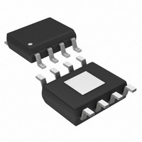
MAX13411EESA+ Maxim Integrated Products, MAX13411EESA+ Datasheet - Page 17

MAX13411EESA+
Manufacturer Part Number
MAX13411EESA+
Description
IC TXRX RS-485 LDO/CTRL 8-SOIC
Manufacturer
Maxim Integrated Products
Type
Transceiverr
Datasheet
1.MAX13410EESA.pdf
(24 pages)
Specifications of MAX13411EESA+
Number Of Drivers/receivers
1/1
Protocol
RS485
Voltage - Supply
6 V ~ 28 V
Mounting Type
Surface Mount
Package / Case
8-SOIC (3.9mm Width) Exposed Pad, 8-eSOIC. 8-HSOIC
Lead Free Status / RoHS Status
Lead free / RoHS Compliant
may not be necessary. In these cases, the drive current
can be reduced to minimize the die temperature.
Minimizing the load on the V
power dissipation of the part and ultimately reduces the
maximum die temperature.
θ
is independent of the MAX13410E–MAX13415E.
primarily a characteristic of the circuit-board design. The
CA
RS-485 Transceiver with Integrated Low-Dropout
is the thermal resistance from case to ambient and
Functional Diagram for the MAX13410E/MAX13411E/MAX13414E/MAX13415E
______________________________________________________________________________________
RO
RE
DE
DI
REG
Regulator and AutoDirection Control
1
2
4
3
+
1
2
3
4
output lowers the
R
MAX13410E
MAX13411E
RO
V
DI
RE
REG
D
LDO
MAX13412E
MAX13413E
RI
DI
MACHINE
8
7
6
5
STATE
Functional Diagram for the MAX13412E/MAX13413E
θ
CA
V
B
A
GND
CC
θ θ
CA
is
V
REG
largest contributing factor of
weight of the copper connected to the exposed paddle
of the MAX13410E–MAX13415E. Lower the thermal
resistance by using as large a pad as possible.
Additionally, vias can be used to connect the pad to
other ground planes in the circuit board.
Note that
junction-to-case temperature and is fixed at 6.0°C/W. It is
solely based on the die and package characteristics of
DE/RE
RE
COM
V
V
DE
D
REG
REG
RO
R
DI
V
+
REG
-
1
2
4
3
+
-
LDO
V
DT
+
R
MAX13414E
MAX13415E
θ
JC
D
V
GND
is the thermal resistance of the part from
CC
B
A
LDO
8
7
6
5
6
8
7
5
Functional Diagrams
V
B
A
GND
CC
θ
CA
will be the size and
17


