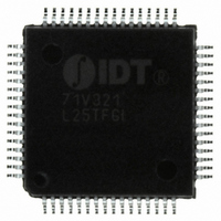
IDT82V1054APF IDT, Integrated Device Technology Inc, IDT82V1054APF Datasheet - Page 24

IDT82V1054APF
Manufacturer Part Number
IDT82V1054APF
Description
IC PCM CODEC 4CH MPI 3.3V 64TQFP
Manufacturer
IDT, Integrated Device Technology Inc
Type
Line Interface Units (LIUs)r
Datasheet
1.IDT82V1054APF8.pdf
(42 pages)
Specifications of IDT82V1054APF
Voltage - Supply
3.135 V ~ 3.465 V
Mounting Type
Surface Mount
Package / Case
64-TQFP, 64-VQFP
Lead Free Status / RoHS Status
Contains lead / RoHS non-compliant
Number Of Drivers/receivers
-
Protocol
-
Other names
82V1054APF
Available stocks
Company
Part Number
Manufacturer
Quantity
Price
Company:
Part Number:
IDT82V1054APF
Manufacturer:
IDT, Integrated Device Technology Inc
Quantity:
10 000
Company:
Part Number:
IDT82V1054APF8
Manufacturer:
IDT, Integrated Device Technology Inc
Quantity:
10 000
Company:
Part Number:
IDT82V1054APFG
Manufacturer:
IDT, Integrated Device Technology Inc
Quantity:
10 000
Company:
Part Number:
IDT82V1054APFG8
Manufacturer:
IDT, Integrated Device Technology Inc
Quantity:
10 000
IDT82V1054A QUAD PROGRAMMABLE PCM CODEC WITH MPI INTERFACE
GREG8: SLIC Ring Trip Setting and Control, Read/Write (27H/A7H)
GREG9: SI Data, Read Only (28H)
The PCM data Offset Configuration bits (OC[2:0]) determine that the transmit and receive time slots of PCM data offset from the FS
signal by how many periods of BCLK:
OC[2:0] = 000:
OC[2:0] = 001:
OC[2:0] = 010:
OC[2:0] = 011:
OC[2:0] = 100:
OC[2:0] = 101:
OC[2:0] = 110:
OC[2:0] = 111:
The Output Polarity Indicator bit (OPI) indicates the valid polarity of output:
OPI = 0:
OPI = 1:
The Input Polarity Indicator bit (IPI) indicates the valid polarity of input:
IPI = 0:
IPI = 1:
The Input Selection bit (IS) determines which input will be selected as the off-hook indication signal source.
IS = 0:
IS = 1:
The Ring Trip Enable bit (RTE) enables or disables the ring trip function block:
RTE = 0:
RTE = 1:
The Output Selection bits (OS[2:0]) determine which output will be selected as the ring control signal source.
OS[2:0] = 000 - 010:
OS[2:0] = 011:
OS[2:0] = 100:
OS[2:0] = 101:
OS[2:0] = 110:
OS[2:0] = 111:
The SIA[3:0] bits contain the debounced data (off-hook status) on the SI1 pins of Channel 4 to Channel 1 respectively.
The SIB[3:0] bits contain the debounced data (ground key status) on the SI2 pins of Channel 4 to Channel 1 respectively.
Command
Command
I/O data
I/O data
SIB[3]
R/W
OPI
b7
b7
0
SB2 is selected (when SB2 is configured as an output);
SB3 is selected (when SB3 is configured as an output);
0 period of BCLK (default);
1 period of BCLK;
2 periods of BCLK;
3 periods of BCLK;
4 periods of BCLK;
5 periods of BCLK;
6 periods of BCLK;
7 periods of BCLK.
the selected output pin changes from high to low to activate the ring (default);
the selected output pin changes from low to high to activate the ring.
active low (default);
active high.
SI1 is selected (default);
SI2 is selected.
the ring trip function block is disabled (default);
the ring trip function block is enabled.
not defined;
SB1 is selected (when SB1 is configured as an output);
SO1 is selected;
SO2 is selected.
Reserved
SIB[2]
b6
b6
0
0
SIB[1]
IPI
b5
b5
1
1
SIB[0]
24
b4
b4
IS
0
0
SIA[3]
RTE
b3
b3
0
1
OS[2]
SIA[2]
b2
b2
1
0
SIA[1]
OS[1]
b1
b1
INDUSTRIAL TEMPERATURE
1
0
SIA[0]
OS[0]
b0
b0
1
0


