MRF275G M/A-COM Technology, MRF275G Datasheet - Page 18
MRF275G
Manufacturer Part Number
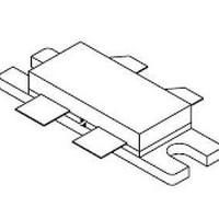
MRF275G
Description
RF MOSFET Power 5-500MHz 150Watts 28Volt 10dB
Manufacturer
M/A-COM Technology
Datasheet
1.MRF275G.pdf
(19 pages)
Specifications of MRF275G
Configuration
Dual
Drain-source Breakdown Voltage
65 V
Gate-source Breakdown Voltage
40 V
Continuous Drain Current
26 A
Power Dissipation
400 W
Maximum Operating Temperature
+ 150 C
Package / Case
Case 375-04
Minimum Operating Temperature
- 65 C
Transistor Polarity
N-Channel
Lead Free Status / Rohs Status
Details
Available stocks
Company
Part Number
Manufacturer
Quantity
Price
Company:

Part Number:
MRF275G
Manufacturer:
M/A-COM
Quantity:
5 000


18
ADVANCED: Data Sheets contain information regarding a product M/A-COM Technology Solutions
is considering for development. Performance is based on target specifications, simulated results,
and/or prototype measurements. Commitment to develop is not guaranteed.
PRELIMINARY: Data Sheets contain information regarding a product M/A-COM Technology
Solutions has under development. Performance is based on engineering tests. Specifications are
typical. Mechanical outline has been fixed. Engineering samples and/or test data may be available.
Commitment to produce in volume is not guaranteed.
The RF MOSFET Line
150W, 500MHz, 28V
MRF275G
tially capacitors. Circuits that leave the gate open–circuited
or floating should be avoided. These conditions can result in
turn–on of the devices due to voltage build–up on the input
capacitor due to leakage currents or pickup.
nalmonolithic zener diode from gate–to–source. If gate pro-
tection is required, an external zener diode is recommended.
Using a resistor to keep the gate–to–source impedance low
also helps damp transients and serves another important
function. Voltage transients on the drain can be coupled to
the gate through the parasitic gate–drain capacitance. If the
gate–to–source impedance and the rate of voltage change
on the drain are both high, then the signal coupled to the
gate may be large enough to exceed the gate–threshold
voltage and turn the device on.
HANDLING CONSIDERATIONS
antistatic bags or conductive foam. Upon removal from the
packaging, careful handling procedures should be adhered
to. Those handling the devices should wear grounding
straps and devices not in the antistatic packaging should be
kept in metal tote bins. MOSFETs should be handled by the
case and not by the leads, and when testing the device, all
leads should make good electrical contact before voltage is
applied. As a final note, when placing the FET into the sys-
tem it is designed for, soldering should be done with
grounded equipment.
DESIGN CONSIDERATIONS
Gate Termination — The gates of this device are essen-
Gate Protection — These devices do not have an inter-
When shipping, the devices should be transported only in
The MRF275G is a RF power N–channel enhancement
M/A-COM Technology Solutions Inc. and its affiliates reserve the right to make
changes to the product(s) or information contained herein without notice.
mode field–effect transistor (FETs) designed for HF, VHF
and UHF power amplifier applications. M/A-COM RF MOS-
FETs feature a vertical structure with a planar design. M/A-
COM Application Note AN211A, FETs in Theory and Prac-
tice, is suggested reading for those not familiar with the con-
struction and characteristics of FETs. The major advantages
of RF power FETs include high gain, low noise, simple bias
systems, relative immunity from thermal runaway, and the
ability to withstand severely mismatched loads without suf-
fering damage. Power output can be varied over a wide
range with a low power dc control signal.
DC BIAS
fore, does not conduct when drain voltage is applied. Drain
current flows when a positive voltage is applied to the gate.
RF power FETs require forward bias for optimum perform-
ance. The value of quiescent drain current (IDQ) is not criti-
cal for many applications. The MRF275G was characterized
at IDQ = 100 mA, each side, which is the suggested mini-
mum value of IDQ. For special applications such as linear
amplification, IDQ may have to be selected to optimize the
critical parameters. The gate is a dc open circuit and draws
no current. Therefore, the gate bias circuit may be just a
simple resistive divider network. Some applications may
require a more elaborate bias system.
GAIN CONTROL
rated value down to zero (negative gain) by varying the dc
gate voltage. This feature facilitates the design of manual
gain control, AGC/ALC and modulation systems.
• North America Tel: 800.366.2266 / Fax: 978.366.2266
• Europe Tel: 44.1908.574.200 / Fax: 44.1908.574.300
• Asia/Pacific Tel: 81.44.844.8296 / Fax: 81.44.844.8298
Visit www.macomtech.com for additional data sheets and product information.
The MRF275G is an enhancement mode FET and, there-
Power output of the MRF275G may be controlled from its
M/A-COM Products
Released - Rev. 07.07
Related parts for MRF275G
Image
Part Number
Description
Manufacturer
Datasheet
Request
R
