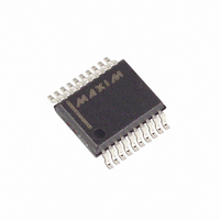
MAX3218EAP+T Maxim Integrated Products, MAX3218EAP+T Datasheet - Page 5

MAX3218EAP+T
Manufacturer Part Number
MAX3218EAP+T
Description
IC TXRS RS-232 W/SHTDWN 20SSOP
Manufacturer
Maxim Integrated Products
Type
Line Transceiverr
Datasheet
1.MAX3218CAP.pdf
(12 pages)
Specifications of MAX3218EAP+T
Number Of Drivers/receivers
2/2
Protocol
RS232
Voltage - Supply
1.8 V ~ 4.25 V
Mounting Type
Surface Mount
Package / Case
20-SSOP
Lead Free Status / RoHS Status
Lead free / RoHS Compliant
The MAX3218 line driver/receiver is intended for bat-
tery-powered EIA/TIA-232 and V.28/V.24 communica -
tions interfaces that require two drivers and two
receivers. The operating voltage extends from 1.8V to
4.25V, yet the device maintains true RS-232 and
EIA/TIA-562 transmitter output voltage levels. This wide
supply voltage range permits direct operation from a
variety of batteries without the need for a voltage regu-
lator. For example, the MAX3218 can be run directly
from a single lithium cell or a pair of alkaline cells. It
can also be run directly from two NiCd or NiMH cells
from full-charge voltage down to the normal 0.9V/cell
end-of-life point. The 4.25V maximum supply voltage
allows the two rechargeable cells to be trickle- or fast-
charged while driving the MAX3218.
The circuit comprises three sections: power supply,
transmitters, and receivers. The power-supply section
converts the supplied input voltage to 6.5V, providing the
voltages necessary for the drivers to meet true RS-232
levels. External components are small and inexpensive.
The transmitters and receivers are guaranteed to oper-
ate at 120kbps data rates, providing compatibility with
LapLink™ and other high-speed communications soft-
ware.
______________________________________________________________Pin Description
_______________Detailed Description
5, 17, 20
11, 12
13, 14
16, 18
9, 10
PIN
7, 8
15
19
1
2
3
4
6
1µA Supply Current, 1.8V to 4.25V-Powered
R1OUT, R2OUT
T2OUT, T1OUT
FORCEOFF
RS-232 Transceiver with AutoShutdown™
R2IN, R1IN
FORCEON
T1IN, T2IN
C1-, C1+
INVALID
NAME
_______________________________________________________________________________________
GND
V
V+
LX
V-
CC
Inductor/Diode Connection Point
Output of Invalid Signal Detector. Low if invalid RS-232 levels are present on all receiver inputs,
otherwise high.
Drive high when FORCEOFF = high to override automatic circuitry, keeping transmitters on.
Drive low to shut down transmitters and on-board power supply, overriding all automatic
circuitry and FORCEON.
Ground
Supply Voltage Input, 1.8V to 4.25V. Bypass to GND with at least 1µF.
Transmitter Inputs
Receiver Outputs
Receiver Inputs
Transmitter Outputs, swing between V+ and V-
Negative Supply generated on-board
Terminal for Charge-Pump Capacitor
Positive Supply generated on-board
The MAX3218 is equipped with Maxim’s new propri -
etary AutoShutdown™ circuitry. This achieves a 1µA
supply current by shutting down the device when the
RS-232 cable is disconnected or when the connected
peripheral transmitters are turned off. While shut down,
both receivers can remain active or can be disabled
under logic control. With this feature, the MAX3218 can
be in low-power shutdown mode and still monitor activi-
ty on external devices. Three-state drivers are provid-
ed on both receiver outputs.
Three-state drivers on both receiver outputs are provid-
ed so that multiple receivers, generally of different inter-
face standards, can be wire-ORed at the UART.
The switch-mode power supply uses a single inductor
with one diode and three small capacitors to generate
±6.5V from an input voltage in the 1.8V to 4.25V range.
Use a 15µH inductor with a saturation current rating of at
least 350mA and less than 1 Ω resistance. Table 1 lists
suppliers of inductors that meet the 15 µH/350mA/1Ω
specifications.
™ LapLink is a trademark of Traveling Software, Inc.
AutoShutdown is a trademark of Maxim Integrated Products.
FUNCTION
Switch-Mode Power Supply
Inductor Selection
5


