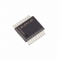
MAX3218EAP+T Maxim Integrated Products, MAX3218EAP+T Datasheet - Page 8

MAX3218EAP+T
Manufacturer Part Number
MAX3218EAP+T
Description
IC TXRS RS-232 W/SHTDWN 20SSOP
Manufacturer
Maxim Integrated Products
Type
Line Transceiverr
Datasheet
1.MAX3218CAP.pdf
(12 pages)
Specifications of MAX3218EAP+T
Number Of Drivers/receivers
2/2
Protocol
RS232
Voltage - Supply
1.8 V ~ 4.25 V
Mounting Type
Surface Mount
Package / Case
20-SSOP
Lead Free Status / RoHS Status
Lead free / RoHS Compliant
MAX3218 shuts down after sensing invalid RS-232 levels
for greater than 30 µs, ensuring that the AutoShutdown
mode is not enabled for slow-moving signals (>1V/µs).
Another system with AutoShutdown may need a period
of time to wake up. Figure 5 shows a circuit that forces
the transmitters on for 100ms after start-up, allowing
enough time for the other system to realize that the
MAX3218 system is awake. If the other system outputs
valid RS-232 signals within that time, the RS-232 ports on
both systems remain enabled.
The MAX3218 is intended for use with three different
power-supply sources: it can be powered directly from
a battery, from a 3.0V or 3.3V power supply, or simulta-
neously from both. Figure 1 shows the single-supply
configuration. Figure 6 shows the circuit for operation
from both a 3V supply and a raw battery supply—an
ideal configuration where a regulated 3V supply is
being derived from two cells. In this application, the
MAX3218’s logic levels remain appropriate for interface
with 3V logic, yet most of the power for the MAX3218 is
1µA Supply Current, 1.8V to 4.25V-Powered
RS-232 Transceiver with AutoShutdown™
Figure 3. AutoShutdown Logic
8
__________Applications Information
FORCEOFF
FORCEON
_______________________________________________________________________________________
Operation from Regulated/Unregulated
R_IN
INVALID IS AN INTERNALLY GENERATED SIGNAL
THAT IS USED BY THE AUTOSHUTDOWN LOGIC
AND APPEARS AS AN OUTPUT OF THE DEVICE.
POWER DOWN IS ONLY AN INTERNAL SIGNAL.
IT CONTROLS THE OPERATIONAL STATUS OF
THE TRANSMITTERS AND THE POWER SUPPLIES.
+0.3V to +2.8V
-0.3V to -2.8V
Dual System Power Supplies
+
+
-
-
Rx
•
•
•
R_OUT
•
•
•
FORCEOFF
FORCEON
DELAY
30µs
drawn directly from the battery, without suffering the
efficiency losses of the DC-DC converter. This pro -
longs battery life.
Bypass the input supplies with 0.1µF at V
least 1µF at the inductor (C5). Increase C5 to 4.7µF if
the power supply has no other bypass capacitor con-
nected to it.
The following suggestions will help you get maximum
life out of your batteries.
Transmit at the highest practical data rate. Although
this raises the supply current while transmission is in
progress, the transmission will be over sooner. If the
MAX3218 is shut down (using FORCEOFF ) as soon as
each transmission ends, this practice will save energy.
Operate your whole system from the raw battery volt-
age rather than suffer the losses of a regulator or DC-
DC converter. If this is not possible, but your system is
powered from two cells and employs a 3V DC-DC con-
verter to generate the main logic supply, use the circuit
of Figure 6. This circuit draws most of the MAX3218’s
power straight from the battery, but still provides logic-
level compatibility with the 3V logic.
FORCEOFF
0
0
0
0
1
1
1
1
INVALID
FORCEON
0
0
1
1
0
0
1
1
Low-Power Operation
INVALID
0
1
0
1
0
1
0
1
POWER DOWN
CC
POWER DOWN
0
0
0
0
0
1
1
1
(C4) and at


