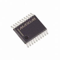
MAX13223EEUP+T Maxim Integrated Products, MAX13223EEUP+T Datasheet - Page 7

MAX13223EEUP+T
Manufacturer Part Number
MAX13223EEUP+T
Description
IC TXRX RS-232 2TX/2RX 20-TSSOP
Manufacturer
Maxim Integrated Products
Type
Transceiverr
Datasheet
1.MAX13223EEUP.pdf
(12 pages)
Specifications of MAX13223EEUP+T
Number Of Drivers/receivers
2/2
Protocol
RS232
Voltage - Supply
3 V ~ 5.5 V
Mounting Type
Surface Mount
Package / Case
20-TSSOP
Lead Free Status / RoHS Status
Lead free / RoHS Compliant
Figure 2 shows the receiver test circuit. Figure 3 shows
driver propagation delay and Figure 4 shows receiver
propagation delay.
The MAX13223E internal power supply consists of a
dual-mode regulated charge pump that provides output
voltages of +5.5V (doubling charge pump) and -5.5V
(inverting charge pump), regardless of the input volt-
age (V
pumps operate in a discontinuous mode. If the output
voltages are less than 5.5V, the charge pumps are
enabled. If the output voltages exceed 5.5V, the charge
pumps are disabled. Each charge pump requires a fly-
ing capacitor (C1, C2) and a reservoir capacitor (C3,
C4) to generate the V+ and V- supplies.
PIN
10
11
12
13
14
15
16
17
18
19
20
1
2
3
4
5
6
7
8
9
CC
Dual Charge-Pump Voltage Converter
FORCEOFF
FORCEON
INVALID
) over the +3.0V to +5.5V range. The charge
R2OUT
R1OUT
T2OUT
T1OUT
NAME
R2IN
R1IN
GND
T2IN
T1IN
C1+
C2+
V
C1-
C2-
EN
V+
V-
CC
_______________________________________________________________________________________
Receiver Enable Control Input. Drive EN low for normal operation. Drive EN high to force the receiver outputs
(R1OUT, R2OUT) into a high-impedance state.
Positive Terminal of the Voltage Doubler Charge-Pump Capacitor
+5.5V Generated by Charge Pump
Negative Terminal of the Voltage Doubler Charge-Pump Capacitor
Positive Terminal of Inverting Charge-Pump Capacitor
Negative Terminal of Inverting Charge-Pump Capacitor
-5.5V Generated by Charge Pump
RS-232 Transmitter 2 Output
RS-232 Receiver 2 Input
Receiver 2 Logic Output
Valid Signal Detector Output. INVALID is high if a valid RS-232 level is present on any receiver input.
Transmitter 2 Logic Input
Transmitter 1 Logic Input
Active-High FORCEON Input. Drive FORCEON high to override AutoShutdown, keeping transmitters and
charge pump on (FORCEOFF must be high).
Receiver 1 Logic Output
RS-232 Receiver 1 Input
RS-232 Transmitter 1 Output
Ground
+3.0V to +5.5V Supply Voltage. Bypass V
as possible.
Active-Low FORCEOFF Input. Drive FORCEOFF low to shut down transmitters, receivers, and on-board
charge pumps, overriding AutoShutdown and FORCEON.
Detailed Description
±70V Fault-Protected, 3.0V to 5.5V,
2Tx/2Rx RS-232 Transceiver
CC
with a 0.1µF ceramic capacitor located as close to the device
The transmitters are inverting level translators that convert
logic levels to EIA/TIA-232/V.28 levels. They guarantee a
250kbps data rate with worst-case loads of 3kΩ in parallel
with 1000pF, providing compatibility with PC-to-PC com-
munication software. The MAX13223E can operate at data
rates of 250kbps (max). Transmitters can be paralleled to
drive multiple receivers. When FORCEOFF is driven to
ground, or the AutoShutdown circuitry senses invalid volt-
age levels at all receiver inputs, the transmitters are dis-
abled and the outputs are forced into a high-impedance
state. Figure 5 shows a complete system connection.
The MAX13223E’s receivers convert RS-232 signals to
logic output levels. Both receiver outputs can be three-
stated using the EN input. In shutdown (FORCEOFF or
AutoShutdown), the MAX13223E’s receiver outputs are
active and asserted low if EN = Low (Table 1). Driving
EN high places the receivers’ outputs in a high-imped-
ance state.
FUNCTION
RS-232 Transmitters
Pin Description
RS-232 Receivers
7


