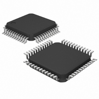
DS3150TN+ Maxim Integrated Products, DS3150TN+ Datasheet - Page 15

DS3150TN+
Manufacturer Part Number
DS3150TN+
Description
IC LIU T3/E3/STS-1 48-TQFP
Manufacturer
Maxim Integrated Products
Type
Line Interface Units (LIUs)r
Datasheet
1.DS3150T.pdf
(28 pages)
Specifications of DS3150TN+
Number Of Drivers/receivers
1/1
Protocol
DS3
Voltage - Supply
3.135 V ~ 3.465 V
Mounting Type
Surface Mount
Package / Case
48-LQFP
Lead Free Status / RoHS Status
Lead free / RoHS Compliant
1.3 Diagnostics
PRBS Generator and Detector. The DS3150 contains on-board pseudorandom bit sequence (PRBS)
generator and detector circuitry for physical layer testing. The device generates and detects unframed
2
generator is enabled through the TDS0 and TDS1 inputs
is always enabled and reports its status on the PRBS output pin. When the PRBS detector is out of
synchronization, the PRBS pin is forced high. When the detector synchronizes to an incoming PRBS
pattern, the PRBS pin is driven low and then pulses high, synchronous with RCLK, for each bit error
detected
package.
Figure 1-6. PRBS Output with Normal RCLK Operation
Figure 1-7. PRBS Output with Inverted RCLK Operation
Loopbacks. The DS3150 has two internal loopbacks
outgoing transmit waveform back to the receiver inputs. This is a local or equipment loopback. During
analog loopback data is transmitted normally on TX+ and TX- but the incoming data on RX+ and RX- is
ignored. The remote loopback loops recovered clock and data back through the LIU transmitter. During
remote loopback, recovered clock and data are output normally on RCLK, RPOS/RNRZ and
RNEG/RLCV, but the TPOS/TNRZ and TNEG pins are ignored. These two loopbacks are invoked using
the LBKS input pin
15
- 1 (DS3 or STS-1) or 2
(Figure 1-6
(Table
and
PRBS
Figure
RCLK
RCLK
PRBS
2-A).
23
- 1 PRBS patterns compliant with the ITU O.151 specification. The PRBS
PRBS Detector
is Not in Sync
PRBS Detector
is Not in Sync
1-7). The PRBS detector and PRBS pin are only available in the TQFP
Signal Pulses High for Each Bit Error Detected
Signal Pulses High for Each Bit Error Detected
ICE = 0 or 1
ICE = Float
PRBS Detector is in sync; the PRBS
PRBS Detector is in sync; the PRBS
15 of 28
(Table 2-A
(Figure
1-1). The analog loopback loops the
and
Table
2-B). The PRBS detector


