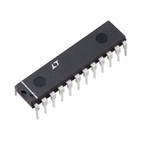
LTC1264CN Linear Technology, LTC1264CN Datasheet - Page 7

LTC1264CN
Manufacturer Part Number
LTC1264CN
Description
IC FILTR BUILDNG BLK HISPD 24DIP
Manufacturer
Linear Technology
Datasheet
1.LTC1264CN.pdf
(16 pages)
Specifications of LTC1264CN
Filter Type
Universal Switched Capacitor
Frequency - Cutoff Or Center
250kHz
Number Of Filters
4
Max-order
2nd
Voltage - Supply
±2.37 V ~ 8 V
Mounting Type
Through Hole
Package / Case
24-DIP (0.300", 7.62mm)
Lead Free Status / RoHS Status
Contains lead / RoHS non-compliant
Available stocks
Company
Part Number
Manufacturer
Quantity
Price
W
optimum mode for high Q designs with f
f
Please refer to the Maximum Frequency of Operation
paragraph under Applications Information for a guide to
the use of capacitor C
V
CENTER
V
IN
IN
ODES OF OPERATIO
Figure 4. Mode 1, 2nd Order Filter Providing Notch,
Bandpass and Lowpass Outputs
Figure 5. Mode 1b, 2nd Order Filter Providing Notch,
Bandpass and Lowpass Outputs
R1
R1
) ratios greater than 20:1.
AGND
AGND
–
+
–
+
R3
R2
R3
R2
C
C
NOTE: R5 ≤ 5k
f
Q =
H
i
C
OLP
=
.
f
R3
R2
CLK
20
f
Q =
H
= –
i
OLP
=
1/4 LTC1264
√
; f
R6
f
(R6 + R5)
R3
R2
R2
R1
CLK
20
N
O
N
= H
1/4 LTC1264
; H
= f
+
R6
(
+
; f
R6 + R5
C
ON
i
ON
C
O
Σ
√
R6
Σ
= f
(R6 + R5)
= –
–
; H
–
S
i
S
; f
R6
ON
R2
R1
)
n
R5
= f
= –
U
∫
; H
∫
O
; f
OBP
R2
R1
CLK
n
= f
; H
= –
O
OBP
to f
R3
R1
BP
BP
= –
∫
CUTOFF
∫
R3
R1
1264 F05
1264 F04
(or
LP
LP
Mode 3
In Mode 3, the ratio of the external clock frequency to the
center frequency of each 2nd order section can be
adjusted above or below 20:1. Figure 6 illustrates Mode 3,
the classical state variable configuration, providing high-
pass, bandpass, and lowpass 2nd order filter functions.
Mode 3 is slower than Mode 1. Mode 3 can be used to
make high order all-pole bandpass, lowpass, and high-
pass filters.
Please refer to the Maximum Frequency of Operation
paragraph under Applications Information for a guide to
the use of capacitor C
Mode 2
Mode 2 is a combination of Mode 1 and Mode 3, shown in
Figure 7. With Mode 2, the clock-to-center frequency ratio,
f
2 is that it provides less sensitivity to resistor tolerances
than does Mode 3. As in Mode 1, Mode 2 has a notch
output which depends on the clock frequency, and the
notch frequency is therefore less than the center fre-
quency, f
Please refer to the Maximum Frequency of Operation
paragraph under Applications Information for a guide to
the use of capacitor C
CLK
V
IN
/f
O
AGND
R1
, is always less than 20:1. The advantage of Mode
Figure 6. Mode 3, 2nd Order Section Providing
Highpass, Bandpass and Lowpass Outputs
O
.
H
–
+
f
i
OHP
=
f
R4
R3
R2
CLK
20
= –
; f
R2
R1
C
C
O
.
.
; H
= f
OBP
i
√
1/4 LTC1264
R2
R4
= –
HP
; Q = 1.005
+
R3
R1
C
C
Σ
(
–
1 –
S
6.42•R4
( )
1
R3
R2
∫
R3
√
R2
R4
)
LTC1264
;
H
(
OLP
1 –
BP
∫
= –
6.42•R4
1
R3
1264 F06
R4
R1
)
1264fb
7
LP


