CC-2401K2A-CS Copeland Communications Inc, CC-2401K2A-CS Datasheet
CC-2401K2A-CS
Specifications of CC-2401K2A-CS
CC-2401K2A-CS


Related parts for CC-2401K2A-CS


CC-2401K2A-CS Summary of contents
Page 1
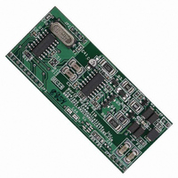
... Vending & gaming machines Description The CC-2401K2 World modem ™ Secure is a compact integrated 2400 baud modem with World Modem™ compatibility. The modem features a transformer-less DAA meeting global telephone system requirements, no electro-mechanical components and flexible DSP data pump. The modem is user-configurable to meet virtually all global telecom requirements. The modem supports serial host communications via flexible internal UART. The modem conforms to the industry standard World Modem™ ...
Page 2
... Modem Result Codes and Call Progress........................................................................ 21 Automatic Call Progress Detection................................................................................ 21 Manual Call Progress Detection .................................................................................... 22 Low Level DSP Control............................................................................................................. 25 DSP registers.................................................................................................................. 25 Call Progress Filters................................................................................................................... 28 CE DECLARATION OF CONFORMITY ............................................................................... 63 Revision Information............................................................................................................... 65 Contact Information................................................................................................................... 66 Warranty..................................................................................................................................... 66 Legal........................................................................................................................................... 66 © 2007, Copeland Communications, Inc. Data Sheet Page CC-2401K2 Datasheet Rev 1.5 CC-2401K2 ...
Page 3
... Block Diagram © 2007, Copeland Communications, Inc. Data Sheet Page CC-2401K2 Datasheet Rev 1.5 CC-2401K2 ...
Page 4
... The pin out of the serial modem is shown in the figure below. The host interface control and data signals are 3.3 volts and are 5 volt tolerant. The World modem II modems can be directly connected into 3 volt systems models (CC-2401K2-xx5), connect pin 61 to 5V. On 3.3V models, connect Pin 61 to +3.3V. ...
Page 5
... The module is designed to plug into 2 mm sockets with the same 24 mm spacing. Due to the low mass of the board, no retention is required aside from the sockets. A large tie -wrap may be used to insure retention in high shock or vibration environments, if desired. © 2007, Copeland Communications, Inc. Data Sheet Page CC-2401K2 Datasheet Rev 1.5 CC-2401K2 ...
Page 6
... Via programmable control registers DTMF & pulse 3.3 V Nominal 3.0V Minimum 3.6V Maximum 25 mA Operating Maximum 100 µA Standby Maximum Commercial 0C-70C (contact factory for extended temperature options) FCC part 15 FCC part 68 EN55022 EN55024 EN61000 T BR-21 Page CC-2401K2 Datasheet Rev 1.5 CC-2401K2 ...
Page 7
... Copeland Communications, Inc. Data Sheet Optional Call Progress Monitor Suggested Component Values Symbol Value C2, C3, C5 0.1 µ ±20% C4 100 µ Elec. ±20% C6 820 pF ±20 k?, 1/10 W, ± 1/10 W, ± k?, 1/1 W, ±5% U1 LM386 Page CC-2401K2 CC-2401K2 Datasheet Rev 1.5 ...
Page 8
... FSK * NOTE: The CC-2401 only adjusts its DCE rate from 2400 bps to 1200 bps connecting to a V.22-only (1200 bps only modem. Because the V.22bis specification does not outline a fallback procedure, the host should implement a fallback mechanism consisting of hanging up and connecting at a lower baud rate. Retraining to accommodate changes in line conditions that occur during a call must be implemented by terminating the call and redialing ...
Page 9
... V.23 (1200 tx, 75 rx) V.23 (75 tx, 1200 rx) The CC-2401 does not continuously check for stop bits on the incoming digital data. If the TXD pin is not high, the RXD pin may echo meaningless characters to the host. This requires the UART to flush its receiver FIFO upon initialization. © ...
Page 10
... Flow control is only needed if the DTE and DCE rate are not the same. If the DTE rate is set higher than the line (DCE), flow control is required to prevent data loss to the transmitter. To control data flow, the CTS pin is used. When CTS is asserted, the CC-2401 is ready to accept a character. While CTS is negated, no data should be sent to the modem on TXD. To simplify flow control, the CC-2401 has an integrated ten character transmit FIFO and allows for two different CTS reporting methods ...
Page 11
... On-Hook Intrusion Detection When the CC-2401 is sharing the telephone line with other devices important that it not interrupt a call in progress. To detect when another device is using a shared telephone line, the host can use the modem to monitor the TIP-RING dc voltage with the LVS[7:0] bits (SDB). This register has a resolution of 1V per bit with an accuracy of about ± ...
Page 12
... AT:I command. Loop Current Detection The CC-2401 can monitor the loss of loop current. This feature can be enabled by setting S08[4] (NLDM This feature is disabled by default. If the loop current is too low for normal DAA operation, S09[4] (NLD) is set. © 2007, Copeland Communications, Inc. ...
Page 13
... The CC-2401 supports full V.23 operation including the V.23 reversing procedure. V.23 operation is enabled by setting S07 (MF1) = xx10xx00 and receives data at 600 or 1200 bps. If S07[4] (V23T the CC-2401 Receives data at 75 bps and transmits data at 600 or 1200 bps. S07[2] (BAUD) is the 1200 or 600 bps indicator. BAUD = 1 1200/600 V.23 channel to run at 1200 bps, while BAUD = 0 When a V.23 connection is established, the modem responds with a “ ...
Page 14
... If the CC-2401 doe not detect more than the 1300 Hz carrier in a time window of 400 ms, it reverses again and waits to detect a 390 Hz carrier for 440 ms. Then if the CC-2401 detects more than 390 Hz carrier in a time window of 220 ms, it sets the S09[7] bit, and the CC-2401 echoes a “c”. ...
Page 15
... RXD. 2. When the CC-2401 detects the stop flag, it sends the last data word in the frame as well as the two CRC bytes and determine if the CRC checksum matches. Thus, the last two bytes are not frame data but are the CRC bytes, which can be discarded by the host. If the checksum matches, the CC-2401 sends “G” ...
Page 16
... The CC-2401 supports a subset of the typical modem AT command set since it is intended for use with a dedicated microcontroller instead of general terminal applications. AT commands begin with the letters “AT” ...
Page 17
... If any character is received by the CC-2401 between the ATDT#<CR> command and when the connection is made (“c” or “d” is echoed), the extra character is interpreted as an abort and the CC-2401 returns to command mode ready to accept AT commands. A line feed character immediately following the <CR> is treated as an extra character and aborts the call. If the modem does not have to dial (ATDT< ...
Page 18
... ATDT1,p12345 If the result code is a “t”, the dialing was accomplished using DTMF dialing. If the result code is “tt”, the dialing was accomplished using pulse dialing. In the above example, the CC-2401 dials the first digit “1” using DTMF. The “,” is used to pause in order to ensure that the central office has had time to accept the DTMF digit “ ...
Page 19
... This command monitors a register in binary format. The byte following the “m” is the address in binary. The CC-2401 constantly transmits the contents of the register at the set baud rate until a new byte is transmitted to the device. The new byte is ignored and viewed as a stop c ommand. The modem result codes should be disabled before using this command ...
Page 20
... The previous message can be resent if the host responds with a “-“ after the CC-2401 echoes a “K”. Any character other than a “!” “~” sent to the modem immediately after the “K” causes the modem to escape to the command mode and remain off hook. Any character except “ ...
Page 21
... The modem, still in command mode, can be placed online as a transmitter by issuing the “ATX2” command or a receiver by issuing the “ATX3” command. If tonal acknowledgement is not used, the host can toggle the ESCAPE pin to place the CC-2401 in command mode and issue an “ATX2” “ATX3” command to reverse data direction. ...
Page 22
... S1B Manual Call Progress Detection Because other call progress tones beyond those described above may exist, the CC-2401 supports manual call progress. This requires the host to read and write the low-level DSP registers and may require realtime control by the host. Manual call progress may be required for detection of application specific ringback, dial tone and busy signals ...
Page 23
... Number>;<CR>”. This causes the modem to dial and return to command mode. Once the host has detected an answer tone using manual call progress, the host should immediately execute the “ATDT” command in order to make a connection. This causes the CC-2401 to search for the modem answer tone and begin the correct connect sequence. ...
Page 24
... D - 941 1633 * B 941 1209 # C 941 1447 A D 697 1633 B E 770 1633 C F 852 1633 Page CC-2401K2 CC-2401K2 Datasheet Rev 1.5 ...
Page 25
... Care must be exercised when writing to DSP registers. DSP registers can only be written while the CC-2401 is on hook and in command mode. Writing to any register address not listed or writing out of range values is likely to cause the DSP to exhibit unpredictable behavior ...
Page 26
... Level = 10log dBm. Level = 10log dBm. Page CC-2401K2 Function Default (dec) (XTML/4096) -10 4096 10 (DTML/4868) -5.5 4868 10 (DTMT/3277) – 2 3277 10 91 (4096/CPDL) -43 4096 10 4987 536 4987 536 (TGNL/2896) 2896 10 4096 10 (2620/CONL) – 10 (3300/COFL) – 3300 10 (AONL/107) – (AOFL/58) – 45 CC-2401K2 Datasheet Rev 1.5 ...
Page 27
... DTMF tone reporting Page CC-2401K2 SE5 Name Description DADL DSP Register address bits [7:0] DDL DSP register data bits [7:0] DSP1 7 = DSP data available 6 = Tone detected 5 = Reversed 4:0 = Tone type DSP2 7 = Reserved 6:3 = DTMF tone to transmit 2:0 = Tone type CC-2401K2 Datasheet Rev 1.5 ...
Page 28
... B1_a1 0x001E B1_a2 0x001F B2_k0 0x0020 B2_b1 0x0021 B2_b2 0x0022 B2_a1 0x0023 B2_a2 Page CC-2401K2 (dec) 256 -8184 4096 7737 -3801 1236 133 4096 7109 -3565 256 -8184 4096 7737 -3801 1236 133 4096 7109 -3565 CC-2401K2 Datasheet Rev 1.5 ...
Page 29
... Busy tone on. Time that the busy tone must be on (10 ms units) for busy tone detector. Busy tone off. Time that the busy tone must be off (10 ms units) for busy tone detector Page CC-2401K2 Datasheet Rev 1.5 CC-2401K2 Reset 0x00 0x02 0x03 ...
Page 30
... V.22bis 2400 bps scrambled ones length low. Minimum length of time for transmission of 2400 bps scrambled binary ones by a call mode V.22bis modem (5/3 ms units ). Page CC-2401K2 Reset 0x0F 0x26 0x4B 0x07 0x0A 0x03 0x2D 0x5D 0x09 0xA2 0xCB 0x08 0x3C 0x0C 0x78 CC-2401K2 Datasheet Rev 1.5 ...
Page 31
... FSK modem connections (256 x 5/3 ms units). Receive answer tone length. Minimum length of time required for detection of a CCITT answer tone (5/3 ms units). The time after going off hook when the loop current sense bits are checked for overcurrent status (5/3 ms units). ...
Page 32
... This is a bit-mapped register * This is a bit-mapped register * This is a bit-mapped register Line current Status. 8 bit value returning the loop current. Each bit represents 1 loop current. Accuracy is not guaranteed if the loop current is less than required for normal operation Page CC-2401K2 Reset ...
Page 33
... Data Sheet S-Register Summary (Continued) Function * This is a bit-mapped register * This is a bit-mapped register * This is a bit-mapped register * This is a bit-mapped register * This is a bit-mapped register * This is a bit-mapped register Page CC-2401K2 Reset 0x0F 0x00 0xF0 0x00 ---- 0x20 CC-2401K2 Datasheet Rev 1.5 ...
Page 34
... GPIO1[1:0] GPD4 GPD3 GPD2 GPD1 GPE TONE[4:0] TONC[2:0] USEN1 V23E ANSE DTMFE PDDE RCC[2:0] RAS[5:0] RMX[3:0] LM[1:0] HBE FDT CC-2401K2 Datasheet Rev 1.5 Default Binary 0000_0110 0000_0000 0000_0000 0000_0000 0000_0000 0000_0100 0001_0000 0000_0100 0000_0100 0100_0001 0000_1000 0000_1100 0010_0010 0000_0000 0000_0000 0000_0000 ...
Page 35
... V23E ANSE DTMFE PDDE RCC[2:0] RAS[5:0] RMX[3:0] LM[1:0] HBE FDT ARL[1:0] ATL[1:0] ILIM RZ RT ACT[3:0] DCR BTD ROV CC-2401K2 Datasheet Rev 1.5 Default Binary 0000_0110 0000_0000 0000_0000 0000_0000 0000_0000 0000_0100 0001_0000 0000_0100 0000_0100 0100_0001 0000_1000 0000_1100 0010_0010 0000_0000 0000_0000 0000_0000 0000_0000 ...
Page 36
... Reset Settings = 0000_0110 (0x06) Bit Name 7 Reserved Read Returns zero Blind Dialing 0 = Disable 1 = Enabled (blind dialing occurs immediately after “ATDT#” command). 5 V23R V.23 Receive V.23 75 bps send/600 (BAUD = 0) or 1200 (BAUD = 1) bps receive Disable 1 = Enable 4 V23T V.23 Transmit V.23 600 (BAUD = 0) or 1200 (BAUD = 1) bps send/75 bps receive. ...
Page 37
... V.23 Reversal Detect Mask 0 = Change in REV does not affect INT low to high transition in REV (S09, bit 0) activates INT. © 2007, Copeland Communications, Inc. Data Sheet NVDM RIM CIDM OCDM REVM R/W R/W R/W R/W Function Page CC-2401K2 D0 R/W CC-2401K2 Datasheet Rev 1.5 ...
Page 38
... No Phone Line Detect (sticky). No line phone detected. Clears on :I read Ring Indicator (sticky). Active high bit when the CC-2401 is on hook. Indicates ring event has occurred. Clears on :I read. 2 CID Caller ID (sticky). Caller ID preamble has been detected; data soon follows. Clears on :I read. ...
Page 39
... CIDM[1:0] Caller ID Monitor Caller ID monitor disabled Caller ID monitor enabled. CC-2401 must detect channel seizure signal followed by marks in order to report caller ID data. (Normal Bellcore caller ID Reserved Caller ID monitor enabled. CC-2401 must only detect marks in order to report caller ID data. 4 Reserved Read returns zero. 3 9BF Ninth Bit Function ...
Page 40
... Modem is placed on hook if parallel intrusion is detected Disable Enable. 0 EHE Enable Hangup on Escape. Modem is placed on hook if an ESC signal is detected Disable Enable. © 2007, Copeland Communications, Inc. Data Sheet RBTS HER EHB EHI R/W R/W R/W R/W Function Page CC-2401K2 D0 EHE R/W CC-2401K2 Datasheet Rev 1.5 ...
Page 41
... Enable. When set, S0C[6:5] is overwritten by the modem as needed. 1 HDEN HDLC Framing Disable Enable. 0 Reserved Read returns zero. © 2007, Copeland Communications, Inc. Data Sheet DCL[3:0] R/W Function OFHD CIDB HDEN R/W R/W R/W Function Page CC-2401K2 D0 D0 CC-2401K2 Datasheet Rev 1.5 ...
Page 42
... NBE Ninth Bit Enable Disable Enable ninth bit as Escape and ninth bit function (register C). © 2007, Copeland Communications, Inc. Data Sheet EHGE STB BDA[1:0] R/W R/W R/W R/W Function Page CC-2401K2 D0 NBE R/W CC-2401K2 Datasheet Rev 1.5 ...
Page 43
... Reserved Read returns Zero 2:0 CIDG[2:0] Caller ID Gain. The CC-2401 dynamically sets the on hook analog receive gain SF4[6:4] (ARG) to CIDG during a caller ID event (or continuously if S0C[6:5] (CIDM = 11). This field should be set prior to caller ID operation. 000 = 0 dB 001 = 3dB 010 = 6 dB 011 = 9 dB 100 = 12 dB © ...
Page 44
... Intrusion Result Code (“I” and “I”). 0 = Disable Enable. 1 NLR No Phone Line Result Code (“L” and “I”). 0 = Disable Enable Ring Result Code (“R”). 0 = Disable 1 = Enable. © 2007, Copeland Communications, Inc. Data Sheet NLR RR R/W R/W R/W Function Page CC-2401K2 Datasheet Rev 1.5 CC-2401K2 ...
Page 45
... Bit Name 7:4 IST[3:0] Intrusion Settling Time. 0000 = IST equals 1 second. Delay between the time the CC-2401 goes off hook and the off hook intrusion algorithm begins (250 ms units). 3 LCLD Loop Current Loss Detect Disable Enables the reporting of “I” and “L” result codes while off hook. Asserts INT# if GPIO4 (SE2[7:6]) is enabled as INT# ...
Page 46
... Copeland Communications, Inc. Data Sheet DGSR[6:0] R/W Function SD[2:0] R/W R/W Function Page CC-2401K2 Datasheet Rev 1.5 CC-2401K2 D0 D0 ...
Page 47
... Digital Input Digital output ( relay drive Reserved Reserved. * Note used as a GPIO pin; SE4[3] (GPE) must equal zero. © 2007, Copeland Communications, Inc. Data Sheet GPD5 GPIO5 R/W R/W Function GPIO2[1:0] GPIO1[1:0] R/W R/W Function Page CC-2401K2 D0 CC-2401K2 Datasheet Rev 1.5 ...
Page 48
... GPE GPIO1 Enable Disable 1 = Enable GPIO1 to be HDLC end of frame flag. 2:0 Reserved Read returns zero. © 2007, Copeland Communications, Inc. Data Sheet GPD4 GPD3 GPD2 R/W R/W R/W Function GPE R/W Function Page CC-2401K2 D0 GPD1 R/W D0 CC-2401K2 Datasheet Rev 1.5 ...
Page 49
... V.23 forward channel mark 1300 Hz (V23E = 1) V.23 backward channel mark 390 Hz (V23E = 1) User defined frequency 1 (USEN1 = 1) User defined frequency 2 (USEN1 = 1) Call progress filter A detected User defined frequency 3 (USEN2 = 1) User defined frequency 4 (USEN2 = 1) Call progress filter B detected Page CC-2401K2 D0 Priority CC-2401K2 Datasheet Rev 1.5 ...
Page 50
... Tone Type Mute DTMF 2225 Hz Bell mode answer tone with phase reversal 2100 Hz CCITT mode answer tone with phase reversal 2225 Hz Bell mode answer tone without phase reversal 2100 Hz CCITT mode answer tone without phase reversal User defined programmable frequency tone (UFRQ) 1300 Hz V ...
Page 51
... ANSE Answering Tone Reporting Enable Disable Enable the reporting of answer tones. 0 DTMFE DTMF Tone Reporting Enable Disable Enable the reporting of DTMF tones. © 2007, Copeland Communications, Inc. Data Sheet USEN2 USEN1 V23E ANSE Function Page CC-2401K2 D0 DTMFE W CC-2401K2 Datasheet Rev 1.5 ...
Page 52
... Name Type Reset Settings = 0000_0000 (0x00) Bit Name 7:4 Reserved Read returns Zero. 3 PDDE Powerdown DSP Engine Power one Powerdown. 2:0 Reserved Read returns zero. © 2007, Copeland Communications, Inc. Data Sheet PDDE R/W Function Page CC-2401K2 Datasheet Rev 1.5 CC-2401K2 ...
Page 53
... RAS[5:0] bits and the RMX[3:0] bits to be classified as a valid ring signal. RDLY[2:0] 000 001 010 - - - 111 0 Reserved This bit must always be written to zero. © 2007, Copeland Communications, Inc. Data Sheet RCC]2:0] R/W Function Delay 0 ms 256 ms 512 ms 1792 ms Delay 0 ms 256 ms 512 ms 1792 ms Page CC-2401K2 Datasheet Rev 1.5 CC-2401K2 ...
Page 54
... These bits set the minimum ring frequency for a valid ring signal. During ring qualification, a timer is loaded with the RAS[5:0] field upon a TIP/RING event and decrements at a regular rate second or subsequent TIP/RING event occurs after the timer has timed out, the frequency of the ring is too low, and the ring is invalidated. The difference between RAS[5:0 and RMX[5:0] identifies the minimum duration between TIP/RING events to qualify as a ring, in binary-coded increments of 2 ...
Page 55
... TIP/RING events to qualify as a ring, in binary-coded increments of 2.0 ms (nominal). A TIP/RING event typically occurs twice per ring tone period Hz, TIP/RING events would occur every 1/( Hz ms. To calculate the correct RMX[3:0] value for a frequency range [f_min, f_max], the following equation should be used: RMX[3: RAS[5:0] – ...
Page 56
... Read returns zero. 1:0 LM[1:0] Line Mode. These bits determine the line status of the CC-2401 On-hook 01 = Off-hook 10 = On-hook line monitor mode 11 = Reserved * Note: Under normal operation, the CC-2401 internal microcontroller automatically sets these bits appropriately. © 2007, Copeland Communications, Inc. Data Sheet LM[1:0] ...
Page 57
... Billing Tone Enable. When the line-side device detects a billing tone, SF9[3] (BTD is set Disable Enable. 6 PDN Powerdown Normal operation Powerdown the CC-2401. 5 PDL Always write zero to this bit. 4 LVFD Line Voltage Force Disable Normal operation The circuitry that forces the LVS register to all 0s and 3V or less is disabled. This rgister may display unpredictable values at voltages between 0 and 2V ...
Page 58
... All 0s are displayed if the line voltage is 0V. 3 Reserved Do not modify. 2 HBE Hybrid Transmit Path Correct Disable Enable. 1:0 Reserved Do not modify. © 2007, Copeland Communications, Inc. Data Sheet ARL[1:0] ATL[1:0] R/W R/W Function Page CC-2401K2 D0 CC-2401K2 Datasheet Rev 1.5 ...
Page 59
... 19.35 to 23.65 V © 2007, Copeland Communications, Inc. Data Sheet ILIM RZ R/W R/W R/W Function Mean On-Hook Speed Less than 0 ±10% (Meets ETSI standard ±10% (Meets Australian spark quenching specification) RMS RMS Page CC-2401K2 D0 RT R/W CC-2401K2 Datasheet Rev 1.5 ...
Page 60
... V 3. Termination Real 600 ? termination that satisfies the impedance requirements of FCC part 68, JATE, and other countries. Global complex impedance. Complex impedance that satisfies global impedance requirements EXCEPT New Zealand. May achieve higher return loss for countries requiring complex ac termination. ...
Page 61
... Same as ROV, except not sticky. 1 ROV Receive Overload (sticky excessive level detected Excessive input level detected. 0 Reserved Do not modify. © 2007, Copeland Communications, Inc. Data Sheet DCR R/W Function BTD OVL ROV R/W R R/W Function Page CC-2401K2 Datasheet Rev 1.5 CC-2401K2 ...
Page 62
... CTS# pin is negated as soon as a start bit is detected and reasserted when the transmit FIFO is empty CTS# pin is negated when the FIFO is = 70% full and reasserted when the FIFO is = 30% full. 6:0 Reserved Read returns zero. © 2007, Copeland Communications, Inc. Data Sheet Function Page CC-2401K2 Datasheet Rev 1.5 CC-2401K2 ...
Page 63
... FCC Compliance Certification Number: US:COPMM00BCC-xxK2 AC-REN: 0.0B DC-REN: NA Connectors: RJ11C Compliance: FCC Part 15 and Part 68 © 2007, Copeland Communications, Inc. Data Sheet Page CC-2401K2 Datasheet Rev 1.5 CC-2401K2 ...
Page 64
... Manufacturer’s Name: Copeland Communications, Inc. Manufacturer’s Address: 440 Colony Place Gahanna, OH, USA 43230 Type of Equipment: Information Technology Equipment Model No.: CC-xxK2 World Modem II Year of Manufacture: 2004 © 2007, Copeland Communications, Inc. Data Sheet 89/336/EEC with Amending Directives: 92/31/EEC, 93/68/EEC, 98/13/EEC Page CC-2401K2 Datasheet Rev 1 ...
Page 65
... Revision Information Revision 1.0 © 2007, Copeland Communications, Inc. Data Sheet Page CC-2401K2 Datasheet Rev 1.5 CC-2401K2 ...
Page 66
... It is your responsibility to ensure that your application meets with your specifications. No representation or warranty is given and no liability is assumed by Copeland Communications, Incorporated with respect to the accuracy or use of such information, or infringement of patents or other intellectual property rights arising from such use or otherwise. Use of Copeland Communication’ ...