CC-2401K2A-CS Copeland Communications Inc, CC-2401K2A-CS Datasheet - Page 19
CC-2401K2A-CS
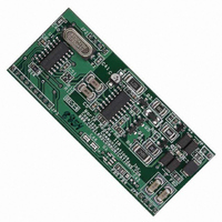
Manufacturer Part Number
CC-2401K2A-CS
Description
MODEM 2400BAUD SECURE 3.3V
Manufacturer
Copeland Communications Inc
Datasheet
1.CC-2401K2A-CS.pdf
(66 pages)
Specifications of CC-2401K2A-CS
Data Format
V.21, V.22, V.23, Bell 103
Baud Rates
2.4k
Interface
UART
Voltage - Supply
3 V ~ 3.6 V
Mounting Type
Surface Mount
Package / Case
Module
For Use With
539-1002 - KIT EVALUATION WORLD MODEM II
Lead Free Status / RoHS Status
Contains lead / RoHS non-compliant
Other names
539-1010
CC-2401K2A-CS
CC-2401K2A-CS


© 2007, Copeland Communications, Inc.
S
w##
This command writes a register in binary format. The first byte following the “w” is the address in binary format
and the second byte is the data in binary format. This is a faster method to write registers than the “SR=N”
command and is recommended for use by a host controller.
r#
This command reads a register in binary format. The byte following the “r” is the address in binary format.
The modem returns the contents of this register in binary format. This is a faster method to read registers than
the “SR?” command and is recommended for use by a host controller.
rm#
This command monitors a register in binary format. The byte following the “m” is the address in binary. The
CC-2401 constantly transmits the contents of the register at the set baud rate until a new byte is transmitted to
the device. The new byte is ignored and viewed as a stop c ommand. The modem result codes should be
disabled before using this command.
q#
This command is the same as the r# command. The response from the CC-2401 is formatted as 0x55
followed by the contents of the register in binary. This guarantees that the register contents are always
preceded by 0x66 and allows the result codes to remain enabled.
V
Z
This command initiates a software reset causing all registers, except E0 to default to their powerup value.
z
The CC-2401 enters a low power mode. In this mode, only the line side of the modem is functional. An
incoming ring signal or line transient causes the modem to power up and send a “R” to the UART. Any other
character received on the RXD pin also causes the modem to exit the wakeup on ring state. Return from wake
on ring cal also be set to trigger the INT# pin by setting S08[6] (WORM) = 1.
Alarm Industry AT Commands
The CC-2401 supports a complete set of commands necessary for making connections in security industry
systems. The CC-2401 is configurable in two modes for these applications. The first mode uses DTMF
messaging and is selected with the “!1” command. The second mode uses FSK transmit with a tone
acknowledgement and is selected by “!2”.
The following are a few general comments about the use of “!” commands. Specific details for each command
are given below. The first instance of the “!” must be on the same line as the ATDT or ATDP command. DRT
must be set to data mode (SE4[5:4](DRT) = 0
three data-mode escape sequence (“+++”, “escape” pin and “ninth-bit”) only function in “!2” mode. However,
SR=N
Writes an S-register. This command writes the value “N” to the S-register specified by “R”. “R” is a
hexadecimal number and “N” must also be a hexadecimal number from 00-FF. This command does not
wait for a carriage return <CR> before taking effect. Two digits must always be entered for both “R” and
“N”.
SR?
Read an S-register. This command causes the CC-2401 to return the value of the S-register specified by
R in hex format. R must be a hexadecimal number. Two digits must always be entered for “R”.
V0
Result codes reported according to Table 14. <SC>
V1
Result codes reported with an additional carriage return and line feeds (default).
Register Control
Write S-Register in Binary
Read S-Register in Binary
Monitor S-Register in Binary
Read S-Register in Binary
Result Code Options
Software Reset
Wakeup on Ring (lower case “z”)
Page 19 of 66
Data Sheet
b
) before attempting to send tones after a “!” command. The
CC-2401K2 Datasheet Rev 1.5
CC-2401K2
Related parts for CC-2401K2A-CS
Image
Part Number
Description
Manufacturer
Datasheet
Request
R

Part Number:
Description:
170 FOOT 24 CONDUCTOR, ST/ST, 100 MICRON, NUMBERED WITH PULLING EYE, INDIVIDUAL FIBERS ARE BUNDLED TOGETHER
Manufacturer:
DIGITHEAD
Part Number:
Description:
Relay; SSR; Cur-Rtg 25 A; Ctrl-V 4-32 VDC; Vol-Rtg 24-280 VAC; Panel; Key Locking Conn
Manufacturer:
Crydom Company
Datasheet:
Part Number:
Description:
Relay; SSR; Cur-Rtg 25 A; Ctrl-V 4-32 VDC; Vol-Rtg 24-280 VAC; Panel; Four Pin Screw
Manufacturer:
Crydom Company
Datasheet:
Part Number:
Description:
Relay; SSR; Cur-Rtg 50 A; Ctrl-V 4-32 VDC; Vol-Rtg 24-280 VAC; Panel; Four Pin Spring
Manufacturer:
Crydom Company
Datasheet:

Part Number:
Description:
CONV DC/DC 3W SNG 24V 3.3V PCB
Manufacturer:
TDK Corporation
Datasheet:
Part Number:
Description:
CONV DC/DC 6W SNGL 24V 12V PCB
Manufacturer:
TDK Corporation
Datasheet:
Part Number:
Description:
CONV DC/DC 6W SNGL 24V 5V PCB
Manufacturer:
TDK Corporation
Datasheet:
Part Number:
Description:
CONV DC/DC 6W SNGL 24V 3.3V PCB
Manufacturer:
TDK Corporation
Datasheet:
Part Number:
Description:
CONV DC/DC 10W SNGL 24V 5V PCB
Manufacturer:
TDK Corporation
Datasheet:

Part Number:
Description:
MODEM 2400BAUD SECURE 5V
Manufacturer:
Copeland Communications Inc
Datasheet:
Part Number:
Description:
MODEM 2400BAUD SERIAL 5V
Manufacturer:
Copeland Communications Inc
Datasheet:
Part Number:
Description:
MODEM 56KBAUD SERIAL V.92 5V
Manufacturer:
Copeland Communications Inc
Datasheet:

Part Number:
Description:
MODEM 2400 BAUD SERIAL
Manufacturer:
Copeland Communications Inc

Part Number:
Description:
MODEM 56K V.92 SERIAL
Manufacturer:
Copeland Communications Inc