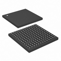
DS33Z11+ Maxim Integrated Products, DS33Z11+ Datasheet - Page 172

DS33Z11+
Manufacturer Part Number
DS33Z11+
Description
IC MAPPER ETHERNET 169-CSBGA
Manufacturer
Maxim Integrated Products
Datasheet
1.DS33Z11.pdf
(172 pages)
Specifications of DS33Z11+
Applications
Data Transport
Interface
SPI/Parallel
Voltage - Supply
1.8V, 3.3V
Package / Case
169-CSBGA
Mounting Type
Surface Mount
Lead Free Status / RoHS Status
Lead free / RoHS Compliant
- Current page: 172 of 172
- Download datasheet (2Mb)
14 REVISION HISTORY
Maxim/Dallas Semiconductor cannot assume responsibility for use of any circuitry other than circuitry entirely embodied in a Maxim/Dallas Semiconductor
product. No circuit patent licenses are implied. Maxim/Dallas Semiconductor reserves the right to change the circuitry and specifications without notice at any
time.
M a x i m I n t e g r a t e d P r o d u c t s , 1 2 0 S a n G a b r i e l D r i v e , S u n n y v a l e , C A 9 4 0 8 6 4 0 8 - 7 3 7 - 7 6 0 0
REVISION
021805
030106
122006
The Maxim logo is a registered trademark of Maxim Integrated Products, Inc. The Dallas logo is a registered trademark of Dallas Semiconductor.
New Product Release.
Added TCLKI to TSER Output Delay Minimum of 3ns.
Added TCLKI to TBSYNC Setup Time Minimum of 3.5ns.
Corrected typo in Table 8-9, Transmit Queue High Threshold entry.
Clarified definition of GL.IDR.ID5-7.
Added definition for BPCLR.PLF[4:0].
Corrected ball assignment shown in the SDATA[3] pin listing for the 100-pin CSBGA package.
Corrected pin description of MDC.
Corrected default value listed in the SU.RMFSRL register definition.
Added Figure 8-11, HDLC Encapsulation of MAC Frame.
Corrected FULLDS pin description for Hardware Mode.
Corrected SU.MACCR.DRO bit description.
Clarified pin description of RMIIMIIS
Clarified pin description of FULLDS
Clarified pin description of H10S
Clarified RMIIMIIS, FULLDS, and H10S internal ties in the 100 pin package.
Clarified Hardware Mode operation with MODEC[1:0] = 10.
Added power supply sequence to the Example Device Initialization Sequence.
Added GL.SDMODE1, GL.SDMODE2, GL.SDMODEWS, and GL.SDRFTC register definitions.
Clarified the GL.C1QPR register definition.
Clarified the 169 Pin package outline drawing and added side view.
Added SU.MACCR.PM and SU.MACCR.PAM bit definitions.
Added GL.SDMODE1, GL.SDMODE2, GL.SDMODEWS, and GL.SDRFTC registers to the
register bit map.
Corrected pin description of RST.
Corrected pin description of REF_CLK
Clarified text regarding use of REF_CLKO in DCE and RMII modes.
Corrected SU.GCR.H10S bit definition.
Corrected the SU.RQLT and SU.RQHT default values to zero.
Clarified section 8.18 on X.86 mode synchronization.
Corrected value of “Receiver Maximum Frame Size” listed in Table 8-9.
Corrected low-power mode information in Section 8.4.
Added D/C operating current maximum values.
Updated D/C operating current typical values.
Added D/C Characteristic entries for Supply currents in “standby” conditions.
Updated package drawings.
© 2006 Maxim Integrated Products
172 of 172
DESCRIPTION
DS33Z11 Ethernet Mapper
Related parts for DS33Z11+
Image
Part Number
Description
Manufacturer
Datasheet
Request
R

Part Number:
Description:
MAX7528KCWPMaxim Integrated Products [CMOS Dual 8-Bit Buffered Multiplying DACs]
Manufacturer:
Maxim Integrated Products
Datasheet:

Part Number:
Description:
Single +5V, fully integrated, 1.25Gbps laser diode driver.
Manufacturer:
Maxim Integrated Products
Datasheet:

Part Number:
Description:
Single +5V, fully integrated, 155Mbps laser diode driver.
Manufacturer:
Maxim Integrated Products
Datasheet:

Part Number:
Description:
VRD11/VRD10, K8 Rev F 2/3/4-Phase PWM Controllers with Integrated Dual MOSFET Drivers
Manufacturer:
Maxim Integrated Products
Datasheet:

Part Number:
Description:
Highly Integrated Level 2 SMBus Battery Chargers
Manufacturer:
Maxim Integrated Products
Datasheet:

Part Number:
Description:
Current Monitor and Accumulator with Integrated Sense Resistor; ; Temperature Range: -40°C to +85°C
Manufacturer:
Maxim Integrated Products

Part Number:
Description:
TSSOP 14/A°/RS-485 Transceivers with Integrated 100O/120O Termination Resis
Manufacturer:
Maxim Integrated Products

Part Number:
Description:
TSSOP 14/A°/RS-485 Transceivers with Integrated 100O/120O Termination Resis
Manufacturer:
Maxim Integrated Products

Part Number:
Description:
QFN 16/A°/AC-DC and DC-DC Peak-Current-Mode Converters with Integrated Step
Manufacturer:
Maxim Integrated Products

Part Number:
Description:
TDFN/A/65V, 1A, 600KHZ, SYNCHRONOUS STEP-DOWN REGULATOR WITH INTEGRATED SWI
Manufacturer:
Maxim Integrated Products

Part Number:
Description:
Integrated Temperature Controller f
Manufacturer:
Maxim Integrated Products

Part Number:
Description:
SOT23-6/I°/45MHz to 650MHz, Integrated IF VCOs with Differential Output
Manufacturer:
Maxim Integrated Products

Part Number:
Description:
SOT23-6/I°/45MHz to 650MHz, Integrated IF VCOs with Differential Output
Manufacturer:
Maxim Integrated Products

Part Number:
Description:
EVALUATION KIT/2.4GHZ TO 2.5GHZ 802.11G/B RF TRANSCEIVER WITH INTEGRATED PA
Manufacturer:
Maxim Integrated Products

Part Number:
Description:
QFN/E/DUAL PCIE/SATA HIGH SPEED SWITCH WITH INTEGRATED BIAS RESISTOR
Manufacturer:
Maxim Integrated Products
Datasheet:


