DP4R60E20B Crydom Co., DP4R60E20B Datasheet - Page 5
DP4R60E20B
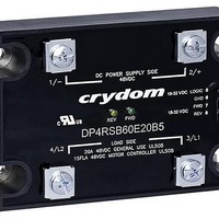
Manufacturer Part Number
DP4R60E20B
Description
RELAY SSR CONTACT 48VDC 20A 32V
Manufacturer
Crydom Co.
Series
DPr
Datasheets
1.DP4R60D20.pdf
(7 pages)
2.DP4R60E20.pdf
(6 pages)
3.DP4R60E20.pdf
(2 pages)
4.DP4R60E20.pdf
(1 pages)
Specifications of DP4R60E20B
Circuit
SPST-NO (1 Form A)
Output Type
DC
On-state Resistance
14 mOhm
Load Current
20A
Voltage - Input
18 ~ 32VDC
Voltage - Load
1 ~ 48 V
Mounting Type
Chassis Mount
Termination Style
Screw Terminal
Package / Case
Hockey Puck
Lead Free Status / Rohs Status
Lead free / RoHS Compliant


Operating Modes
Start: When either FWD or REV Control signal is applied, and after Control Signal Validation Delay, DC
power supply on terminals 1/- and 2/+ is directly connected to Load at terminals 3/L1 and 4/L2 with a
polarity according to the control signal. The start option can be combined with Stop and/or Dynamic
Brake options.
Stop: Load is disconnected from DC power supply. All FET switches (S1, S2, S3 & S4) inside the DP
Series SSC are turned off. This simple Stop option is available only in combination with the simple
Start option (suffix Blank).
Soft Start/Ramp Up: It is a modified Start where the DC power supply is connected to the load using
a 200 Hz pulse width modulation with a duty cycle going from 10% to 100%. Soft Start/Ramp Up time
is defined by SA, SB and SC suffixes. After Soft Start/Ramp Up time is elapsed, the Load will remain
continuously energized for as long as FWD or REV Control signal is applied. This option can be
combined with Soft Stop/Ramp Down and Dynamic Braking modes, but not with simple Stop.
Soft Stop/Ramp Down: It is a modified Stop where the DC power supply is disconnected from the Load
Forward Control
Reverse Control
Start
Dynamic Brake
DP4R60xxxBx
Soft Start/Ramp Up
Soft Stop/Ramp Down
DP4RSx60xxx
Soft Start/Ramp Up
Dynamic Brake
DP4RSx60xxxBx
Control Signals
Load Voltage Signals
Start
Stop
DP4R60xxx
Int : Interlock
t : Control Signal Validation Delay = 0.2 sec, except for Start / Stop (0.025 sec)
t
t
(H)
1
B
: 0.15 sec Break-before-make delay
: Dynamic Brake time
Load voltage signals shown are typical of a DC motor, behavior may change for other load types.
B2: 0.2 sec
B5: 0.5 sec
B8: 0.8 sec
B: Continuous
DP Series
+ V
+ V
+ V
+ V
+ V
+ V
- V
- V
- V
- V
(H)
FWD
DCS
DCS
DCS
DCS
DCS
DCS
DCS
DCS
REV
0
0
0
0
0
0
t
t
t
t
t
ST
t
3 / L1 = +
ST
S1, S4
S1, S4
S1, S4
S1, S4
Complete specifications of these & other Crydom products available at: www.crydom.com
t
t
1
1
t
S3, S4
S3, S4
SP
t
t
B
B
S1, S4
S1, S4
t
t
t
t
t
t
1
1
Int
Int
Int
Int
using a 200 Hz pulse width modulation with a duty cycle going from 100% to 0%. After Soft
Stop/Ramp Down time is elapsed, the Load will remain continuously de-energized waiting for a
new FWD or REV Control signal. Soft Stop/Ramp Down time is tied to Soft Start/Ramp Up time
selected by SA, SB and SC suffixes and can be combined with Soft Start/Ramp Up only.
Dynamic Brake: It could be used as a modified Stop where the FET switches inside the DP Series
SSC are arranged in such a way that they provide a path for the Load Current to keep flowing after
the DC power supply has been disconnected. This mode allows for energy stored in some type of
loads to be discharged. i.e. back EMF on DC motors. Timing for Dynamic Brake is selected by
suffixes B2, B5, B8 and B where the latest will keep the braking or discharging path enabled for
as long as FWD and REV Control signals are removed.
Interlock: It will shut down all FET switches inside the DP Series SSC within 0.2 sec after both
control signals FWD and REV are applied at the same time. An Interlock condition will trigger a
modified Stop such as Soft Stop/Ramp Down or Dynamic Brake whenever an option has been
selected.
t
t
V
V
V
SP
ST
t
t
t
t
DCS
FWD
REV
: Soft Start/Ramp Up time
: Soft Stop/Ramp Down time = t
t
: Reverse Control Signal
SA: 0.2 sec
SB: 0.5 sec
SC: 1 sec
: VDC power supply
ST
: Forward Control Signal
4 / L2 = +
t
ST
S2, S3
S2, S3
t
t
1
1
t
SP
t
B
t
B
S2, S3
ST
S3, S4
t
t
t
t
t
t
1
1
Int
Int
Int
Int
Related parts for DP4R60E20B
Image
Part Number
Description
Manufacturer
Datasheet
Request
R

Part Number:
Description:
RELAY SSR 10-35MA INPUT 16 DIP
Manufacturer:
Crydom Co.
Datasheet:
Part Number:
Description:
RELAY SSR 3.5-10VDC INPUT 16 DIP
Manufacturer:
Crydom Co.
Datasheet:

Part Number:
Description:
RELAY SSR 5A 480VAC SIP
Manufacturer:
Crydom Co.
Datasheet:

Part Number:
Description:
RELAY SSR 12A 240VAC DC
Manufacturer:
Crydom Co.
Datasheet:

Part Number:
Description:
RELAY SSR 25A 240VAC DC
Manufacturer:
Crydom Co.
Datasheet:

Part Number:
Description:
POWER CONTROL SSR 15A DC IN
Manufacturer:
Crydom Co.
Datasheet:
Part Number:
Description:
RELAY SSR 125A 480VAC DC INPUT
Manufacturer:
Crydom Co.
Datasheet:
Part Number:
Description:
RELAY SSR 5A 380VAC AC OUT SIP
Manufacturer:
Crydom Co.
Datasheet:
Part Number:
Description:
RELAY SSR 10A 240VAC DC
Manufacturer:
Crydom Co.
Datasheet:
Part Number:
Description:
RELAY SSR 25A 120VAC AC
Manufacturer:
Crydom Co.
Datasheet:
Part Number:
Description:
RELAY SSR 10-35MA INPUT 16 DIP
Manufacturer:
Crydom Co.
Datasheet:
Part Number:
Description:
RELAY SSR 3.5-10VDC INPUT 16 DIP
Manufacturer:
Crydom Co.
Datasheet:
Part Number:
Description:
RELAY SSR AC 2A 120VAC PNL MNT
Manufacturer:
Crydom Co.
Datasheet:

Part Number:
Description:
RELAY SSR AC OUT 1CH 0.3A PCB
Manufacturer:
Crydom Co.
Datasheet:

Part Number:
Description:
RELAY SSR 3A PC MNT W/SNUBER
Manufacturer:
Crydom Co.
Datasheet: