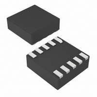
MAX4745ELB+T Maxim Integrated Products, MAX4745ELB+T Datasheet - Page 7

MAX4745ELB+T
Manufacturer Part Number
MAX4745ELB+T
Description
IC SWITCH DUAL SPDT 10UDFN
Manufacturer
Maxim Integrated Products
Datasheet
1.MAX4744ELBT.pdf
(12 pages)
Specifications of MAX4745ELB+T
Function
Audio Switch
Circuit
2 x SPDT
On-state Resistance
950 mOhm
Voltage Supply Source
Single Supply
Voltage - Supply, Single/dual (±)
1.8 V ~ 5.5 V
Current - Supply
0.3µA
Operating Temperature
-40°C ~ 85°C
Mounting Type
Surface Mount
Package / Case
10-µDFN
Lead Free Status / RoHS Status
Lead free / RoHS Compliant
Other names
MAX4745ELB+T
MAX4745ELB+TTR
MAX4745ELB+TTR
The MAX4744/MAX4744H/MAX4745/MAX4745H are
low on-resistance, low-voltage, dual-SPDT analog
switches that operate from a +1.8V to +5.5V single sup-
ply. These devices feature a negative signal capability
that allows signals as low as V
without distortion.
The MAX4744/MAX4745 feature two digital control bits
to control each switch independently (see Table 1). The
MAX4744H/MAX4745H have one control bit to switch
both switches and an enable input EN to put the
switches in a high-impedance mode. Driving EN low
takes the switches out of high impedance and CB0
controls both switches (see Table 2).
The MAX4744/MAX4744H have internal shunt resistors
on all NO and NC terminals to suppress click-and-pop
sounds that can occur when switching audio signals
between pre-charged points.
The MAX4744/MAX4744H/MAX4745/MAX4745H logic
inputs accept up to +5.5V, regardless of supply volt-
age. For example, with a +3.3V supply, CB0, CB1,
CB2, and EN can be driven low to GND and high to
+5.5V, allowing for mixed logic levels in a system.
MAX4744/
MAX4745
—
—
10
1
2
3
4
5
6
7
8
9
PIN
MAX4744H/
MAX4745H
Applications Information
Low-Voltage, Dual SPDT, Audio Clickless
_______________________________________________________________________________________
10
—
—
1
2
3
4
5
6
7
8
9
Switches With Negative Rail Capability
Detailed Description
Digital Control Inputs
NAME
COM2
COM1
GND
NO1
NO2
NC2
NC1
CB1
CB2
CB0
V
EN
CC
CC
- 5.5V to pass through
Digital Control Input for Analog Switch 1
Enable Input. Driving EN high causes all switches to be high impedance. Pull EN low for
normal operation.
Analog Switch 1 – Normally Open Terminal
Ground
Analog Switch 2 – Normally Open Terminal
Digital Control Input for Analog Switch 2
Digital Control Input for Analog Switches 1 and 2
Analog Switch 2 – Common Terminal
Analog Switch 2 – Normally Closed Terminal
Positive Supply Voltage from +1.8V to +5.5V
Analog Switch 1 – Normally Closed Terminal
Analog Switch 1 – Common Terminal
Driving CB0, CB1, CB2, and EN rail-to-rail minimizes
power consumption.
Table 1. MAX4744/MAX4745 Truth Table
Table 2. MAX4744H/MAX4745H Truth Table
X = Don’t Care
CB1
EN
CONTROL
0
0
1
1
CONTROL
0
0
1
CB2
FUNCTION
CB0
0
1
0
1
0
1
X
Connected to NC1
Connected to NC1
Connected to NO1
Connected to NO1
Connected to NO1
Connected to NC1
High Impedance
Switch 1
Switch 1
SWITCH STATE
SWITCH STATE
Pin Description
Connected to NC2
Connected to NO2
Connected to NO2
Connected to NC2
Connected to NO2
Connected to NC2
High Impedance
Switch 2
Switch 2
7


